In the previous project, I have shown you a simple setup for WIFI CONTROLLED LED USING ESP8266 AND ARDUINO. In this project, I will show you How to Control ESP8266 over Internet i.e. controlling ESP8266 from anywhere in the World through Internet.
Outline
ToggleOverview
Even though the main purpose of ESP8266 WiFi Module is to introduce Internet Connectivity into our small DIY Projects, I believe that we haven’t completely utilized the capabilities of the ESP8266 WiFi Module until now i.e. a true IoT (Internet of Things) Project.
I want to take the ESP8266 Projects a step further by actually controlling the ESP8266 over the Internet. In this process, we will learn how to control ESP8266 over Internet by controlling an LED (just to demonstrate the working) connected to one of the GPIO Pins of the ESP8266 WiFi Module over the internet i.e. another network to with the ESP8266 isn’t connected to.
How is this different from the WiFi Controlled LED Project?
Very good question. There are actually two differences between this project and the earlier project. The first difference is how the ESP8266 WiFi Module is controlled. In the previous project, I controlled the ESP8266 through WiFi network i.e. from a computer or phone that is connected to the same network as the ESP8266.
Coming to this project, the aim is to control the ESP8266 over the internet i.e. from a computer or phone anywhere in the World with an internet connectivity.
The second difference is how the ESP8266 WiFi Module is configured. If you remember, I have mentioned particularly that ESP8266 WiFi Module must be flashed with AT Commands Firmware and we will be controlling the ESP8266 through the Program uploaded to Arduino.
But, in this project, I will be directly uploading the code into the ROM of the ESP8266 WiFi Module (the existing program or firmware will be erased).
Now that we have seen the differences, let us proceed with the circuit diagram and the circuit design of the project.
Circuit Diagram
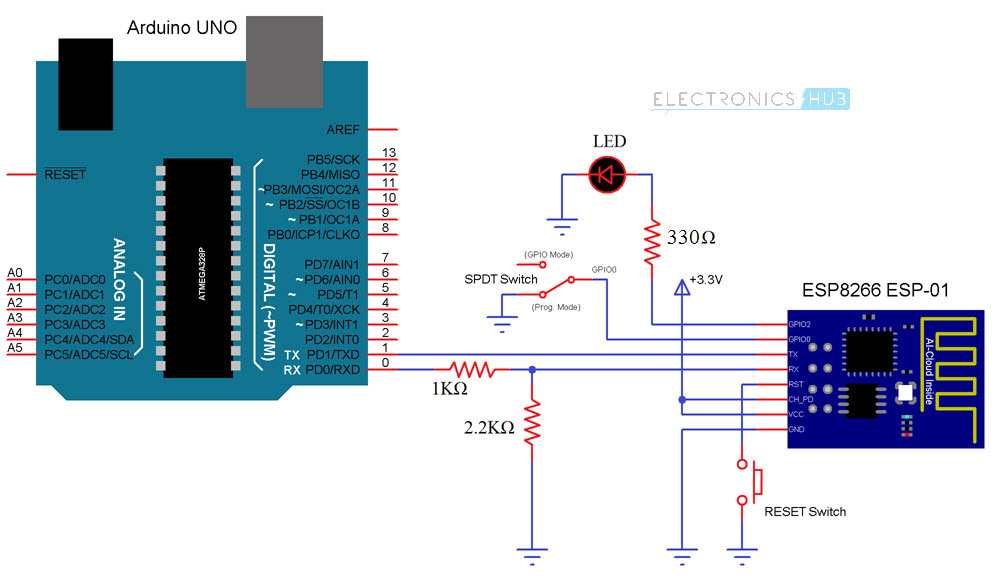
The following circuit is used to control ESP8266 over internet. Let us take a look at the components first and then I will explain the design of the circuit in detail.
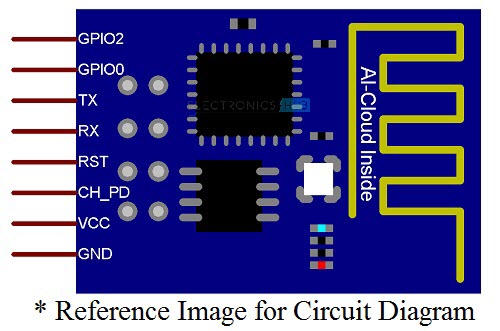
The following image shows the pins of the ESP8266 WiFi Module used in the circuit diagram. For actual pin diagram, please refer to the GETTING STARTED WITH ESP8266 AND ARDUINO Project.
Components Required
- Arduino UNO (as USB to Serial Converter)
- ESP8266 (ESP-01) WiFi Module
- Slide Switch (SPDT Switch)
- Push Button
- 1 KΩ Resistor (1/4 Watt)
- 2.2 KΩ Resistor (1/4 Watt)
- 330 Ω Resistor (1/4 Watt)
- LED
- Connecting Wires
- Mini Breadboard
NOTE:
- Arduino UNO is used as an USB to Serial Converter. So, I have removed the ATmega328p Microcontroller from the Arduino UNO Board. If you have a dedicated USB to Serial Converter (USB-to-TTL), then you won’t need Arduino.
- Also, I have made a simple ESP8266 Breakout Board in an earlier Project called DIY PCB FOR ESP8266. It contain all the important components associated with the ESP8266 WiFi Module. I will be using the same board in this project.
Circuit Design
Connect the VCC and GND of the ESP8266 to 3.3V and GND of the Arduino. The CH_PD pin is also connected to the 3.3V Supply. A Push Button is connected between the Reset Pin and GND.
The TX Pin of the ESP8266 WiFi Module is connected to the TX pin of Arduino and the RX Pin of the ESP8266 is connected to the RX Pin of the Arduino but through a voltage divider consisting of two resistors (1 KΩ and 2.2 KΩ).
An LED is connected to the GPIO2 pin of the ESP8266. Finally, the GPIO0 pin is connected to the Pole of a SPDT Switch (center terminal of the slide switch). One throw terminal of the switch is connected to GND and the other throw terminal is left open but can be used for GPIO connection.
Code
The following program must be uploaded to the ESP8266 WiFi Module. It will setup the WiFi Connection and also creates a simple HTML Page that can be accessed using the IP Address of the ESP8266.
NOTE:
- Before uploading the code to ESP8266, make sure that “Generic ESP8266 Module” is selected in the Arduino Boards section.
- For more information on how to upload a program to ESP8266, refer to the Getting Started with ESP8266 and Arduino Project.
- Enter the details of your WiFi network in the Code.
- I have assigned a Static IP Address for ESP8266 WiFi Module in the code as “192.168.1.254”. I have chosen this address after confirming that there is no other device with this IP Address. You make sure of the same when assigning static IP address.
- Along with the Static IP Address, you must also provide additional information like Default Gateway and Subnet Mask. You can find this by typing “ipconfig” in the command prompt of the Windows.
Working
In order to upload the code, slide the GPIO0 pin to programming mode (connect GPIO0 to GND) and press the RESET Switch. After selecting the correct board and port in the Arduino IDE, upload the code.
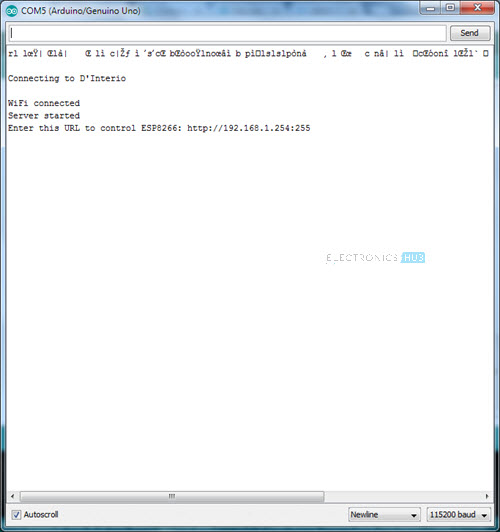
Once the code is uploaded, slide the switch to normal mode and push the RESET button once. Open the serial monitor. There you can see the details of the WiFi Connection.
You can also see the IP Address of the ESP8266 WiFi Module. Since I assigned a Static IP Address, I will get the same. If you have chosen not to assign a static IP Address, then use the address assigned by your router.
In the code, I have created the Server at Port 255. So, the URL of the server will be https://192.168.1.254:255.
Open a web browser in a computer or phone connected to the same WiFi Network and enter the above mentioned URL. A simple HTML page will be opened with few texts and links. The following image is a screenshot of a phone which has opened the URL.
You can click on the specific links to control the LED locally i.e. within the WiFi Network.
How to Control ESP8266 Over Internet?
Now the trick part of controlling the ESP8266 WiFi Module over the Internet. There are two way you can achieve this. One way is to use Port Forwarding, which I will be using in this project and the other way is to use dedicated remote servers like ThingSpeak or aREST.
As I have already set a Static IP Address to my ESP8266 WiFi Module, the next step is to proceed with port forwarding.
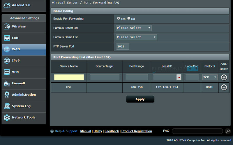
Open your router page from any browser and login using router login details. Go to Port Forwarding page of your router (depends on router, in my case it was I WAN Settings).
Enable Port Forwarding and provide necessary details like Local Server IP Address (static IP Address of ESP8266), Port Number, etc. and save the settings.
Now, go to the Windows Firewall with Advanced Security Settings and add a new inbound rule. Select the rule type for “Port” and specify the port number.
Open any web browser and search for “what is my ip address”. It results in the WAN IP Address of your Router. Note it down.
Now, from another computer (any computer that is not connected to the same WiFi Network as the ESP8266), type the IP Address you just noted down along with the Port number. For example, if your IP Address is 183.92.192.58 and the port number is 255, then type “183.92.192.58:255” in any web browser. You will now get the HTML page to control the LED.
IMPORTANT NOTE:
- Port Forwarding is not recommended as it opens up the computer to outside world and can be easily attacked by virus or malware.
- Also, many ISPs (Internet Service Providers) do not allow port forwarding.
- An alternative is to use the dedicated secure servers like ThingSpeak or aREST.
- In the next project, I’ll show you how to control ESP8266 from the internet using one of those services.


3 Responses
“An alternative is to use the dedicated secure servers like ThingSpeak or aREST.”
Dear Sir,
Could you please give me a tutorial to do this project
Thank you in advanced
For aREST Tutorial, visit: https://www.electronicshub.org/control-a-relay-from-anywhere-in-the-world-using-esp8266/
For ThingSpeak Tutorial, visit: https://www.electronicshub.org/connect-esp8266-to-thingspeak/
What can I use between esp 8266 and out manual switchs to communicate both…and get result on off by our app and switches both…