The next project in the ESP8266 WiFi Module Series is to Control a Relay using ESP8266 and Android through an App (Application) developed with the help of MIT App Inventor. By installing this App in your Android Phone (sorry iOS users!!!), you can control a relay using ESP8266 that is connected to the same WiFi network as your phone.
Overview
ESP8266 WiFi Module has been a main figure in the DIY IoT market. There are several flavours of ESP8266 like ESP-01 by AiThinker, NodeMCU and so forth but the intention and the job are the same.
There are several IoT Projects based on ESP8266 WiFi Module but Home Automation i.e. controlling different electrical appliances through WiFi (or Internet) has always been a trending and in demand project.
So, in this project, I’ll show you how to connect a simple Relay Module to the ESP8266 WiFi Module and also how control a Relay using ESP8266.
For this project, I’ll also create an Android App using which you can control the relay. In order to develop the Android App, I’ll be using MIT App Inventor.
Circuit Diagram
The circuit diagram for the project “Control a Relay using ESP8266” is shown in the image below. You can see that I’ve used a single channel relay module in the circuit diagram.
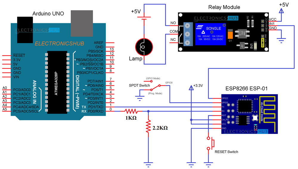
NOTE: If the pins of the Relay Module and the ESP8266 WiFi Module are not clearly visible, I’ll add separate images in the component description section.
Components Required
- ESP8266
- Arduino UNO
- Resistors (1KΩ and 2.2KΩ) – both are ¼ Watt Resistors
- Jumper Wires
- Relay Module
- Small 5V Bulb
- Push Button
- SPDT Switch
- Android App
- Android Phone
- Computer with Internet
Component Description
ESP8266 (ESP-01) WiFi Module: The ESP8266 WiFi Module is responsible for connecting to the WiFi Network and also controlling the Relay Module.
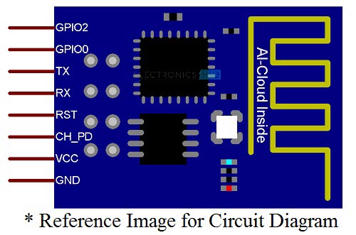
In this project, the ESP8266 Module acts as an HTTP Server. Whenever the client (in this case, the Android App) sends a request, the ESP8266 Servers accepts it and performs relevant operation.
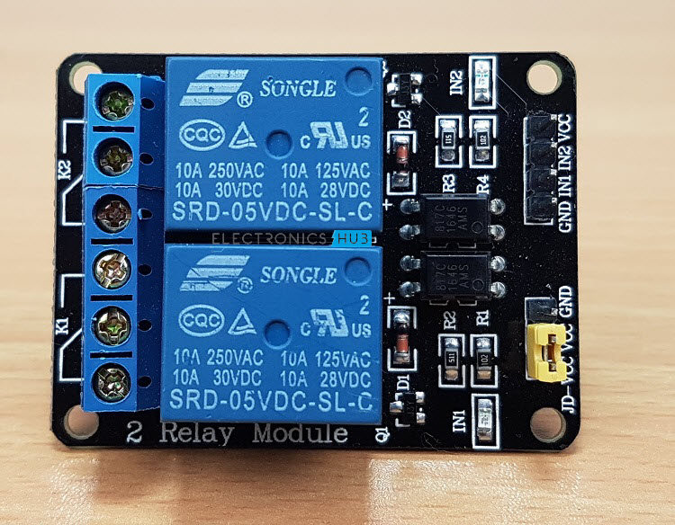
Relay Module: A two channel relay module is used in this project but only a single relay is being used. Although this relay module can be used with AC Supply, I’ve used a small 5V Bulb just to show the output.
Circuit Design
If you notice the circuit diagram, all the connections are similar to that we have already seen in the earlier projects like HOW TO CONTROL ESP8266 OVER INTERNET. I won’t go into the details of all the connections.
The main difference is that the GPIO2 pin of the ESP8266 WiFi Module is connected to the INPUT of the relay.
Code
In order to control a Relay using ESP8266, I’ve used the following code. This code is responsible for connecting the ESP8266 WiFi Module to the specified WiFi Network, assigning a Static IP Address to the ESP8266 Module, creating a simple HTTP Server on ESP8266 and also listen to clients.
IMPORTANT NOTE:
- It is very important that you know what you are doing with Static IP Address. Please double check for the unused (unallocated) IP Address from your router and assign it to the ESP8266.
- I suggest you to upload the program with Static IP Address assigned to ESP8266 (after making necessary changes in the code) so that you can proceed with developing the App.
Android App using MIT App Inventor
MIT App Inventor is an easy way to create simple Application for Android. MIT App Inventor uses Google Account credentials. So, open the App Developer Application using the following URL: MIT APP INVENTOR 2.
After linking your Google Account, create a new project by selecting Project à Start a new Project.
After creating a new project, you will see a screen on which you can layout different objects like Buttons, Sliders, Textbox, etc.
Create an interface similar to the one shown below. It consists of three Buttons, few Labels and a Web Component.
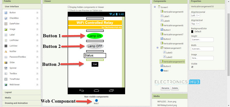
NOTE: The web component can be found in the Connectivity Tab in the Left side.
After arranging all the components and finalizing the App layout, switch to Blocks section from the top right corner.
In the Blocks section, create blocks like shown in the following image. The Static IP Address, which you have assigned in the code, must be entered here in the URL section of the block.
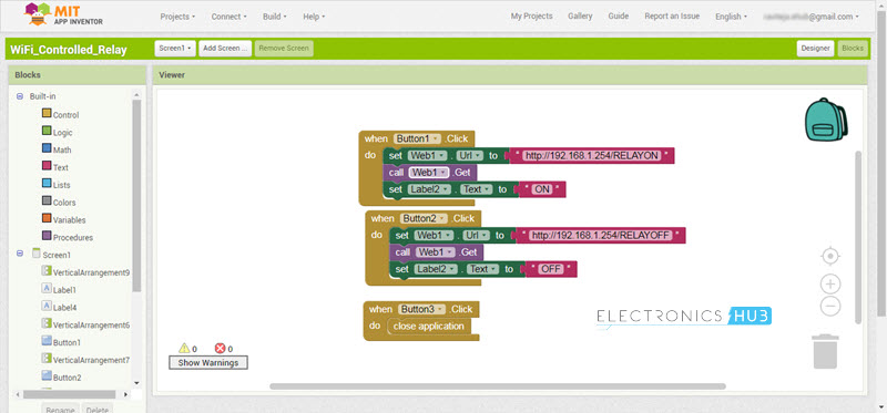
You do not have to create the exact same App. You can finish off with a minimalistic design and interface.
After completing the Blocks section as well, you can debug the App directly from the Browser and an Android Phone without actually installing the App. For this, you have to download and install two Applications: one in your computer and other in your Android Phone.
The software for the Computer is called as MIT_Appinventor_Tools and the App for the Android phone is called MIT AI2 Companion.
I will not go into the details of this, but if you want further information, you can find it here.
Finally, after you are done with the interface, blocks and debugging (if any) of the App, you can download the .apk file to your computer and install it on to your device (Android Phone).
NOTE: To download .apk file, go to Build and select App (save .apk to my computer).
Working
First, make all the necessary connections as per the circuit diagram and upload the program to the ESP8266 WiFi Module.
After the program is uploaded, you will get a confirmation message regarding WiFi connection and Static IP Address. Now open the Android App which we developed using MIT App Inventor 2 and installed it on your Android Phone.
If everything goes well, when you hit the “Lamp ON” button on the App, the Relay gets a Logic LOW signal and the Lamp is turned ON. Similarly, when the “Lamp OFF” button is pressed, the Lamp turn off.
NOTE: The Relay Module used in this project is an Active LOW one.
Applications
- In this project, we have seen how to control a relay using ESP8266 through WiFi with the help of an Android App developed using MIT App Inventor 2 Application.
- Such projects can be the stepping stone for complex home automation system, where the maker can not only assemble the circuit but also make his own Android Application.
- The next big step of this project would be controlling the relay from anywhere in the World i.e. a true Web Controlled Relay.

11 Responses
Hi sir, thanks for this helpful tutorial actually I am a beginner at coding, so I don’t know that much.
can you please tell me what should I change in this code? regard the wifi ID and pass of my router what else ?? I also checked the IP address of my router and it’s same as yours.
also, I want to ask you, is it ok if I use ESP 8266-01 s? rather than ESP8266-01
I will be so thankful if you replay back as soon as you can Sir because it’s urgent, thanks again.
Dear sir,
Thanks for the project . I will tested out. where i can download the Library files and Do you have any code /project to populate DTH11 temp & humidity sensor out put
For ESP8266 and DHT11 -> https://www.electronicshub.org/dht11-humidity-sensor-with-esp8266/
Hi sir, thanks for this helpful tutorial actually I am a beginner at coding,
I would like know u have created project for DTH11 humidity and temprature with relay control function.where i can download latest library for esp8266
From where #include library being downloaded. I am not getting proper github link to download
If you mean the #include, it is part of the ESP8266 board (automatically added to the library when you add the board).
Can I know is the ESP 8266 coding is same with the wifi shield to control the relay?
Video how to control relay using esp8266 WiFi you tube
Hello sir, How to connect to an available wifi network from the app itself by selecting the available wifi network and provide password from there without giving ssid and password in the program?
how to get the list of available wifi network in the app?
How to connect ESP8266 to an available WiFi network from the app itself by selecting the available WiFi network and provide password from the app without giving SSID and password in the program?
how to get the list of available WiFi network in the app.
i need solution for error ESP8266WiFiType.h:26:19: fatal error: queue.h: No such file or directory