Let us continue exploring the ESP8266 Module by making a project to Control a Relay from anywhere in the World using ESP8266. All you need is an account in the aREST application and a web browser with internet connectivity (after setting up the hardware i.e. Arduino, ESP8266 and Relay Module).
Overview
In the previous ESP8266 project called CONTROL A RELAY USING ESP8266 AND ANDROID, I have shown you how to control a relay module (subsequently, the load connected to the relay) through WiFi with the help of ESP8266 and an Android App developed using MIT App Inventor 2 Application.
Even though it is a wonderful project, where you develop your own Android App and control the Relay Module using that App, the main limitation of that project is its scope of connectivity.
To be clearer, the Android Phone (on which the App is installed) and the ESP8266 Module (to which the Relay is connected to) must be connected to the same WiFi Network. If you try to control it outside the WiFi Network of the ESP Module, then you’ll end up being disappointed.
So, in this project, we will take the previous project a step further by seeing how to control a relay from anywhere in the World. Yes. That’s right. You can Control a Relay from anywhere in the World with just a Web Browser.
In order to achieve this, I’ll be using a unique platform called aREST. Using aREST with ESP8266, you can easily implement a true IoT Home Automation Project.
A Brief Note on aREST
The main aim behind the development of the aREST platform is to take the concepts of IoT and Home Automation closer to the DIY Community.
Using the aREST Platform, you can create web-based applications and control different types of boards like Arduino, ESP8266 and Raspberry Pi from anywhere in the World.
In order to use the aREST Platform, all you need is an account in the aREST (not mandatory, I’ll explain in the Working), and a few libraries for the ESP8266 (or Arduino). That’s it.
More information on aREST and how to use it with ESP8266 will be explained in the later sections.
Circuit Diagram
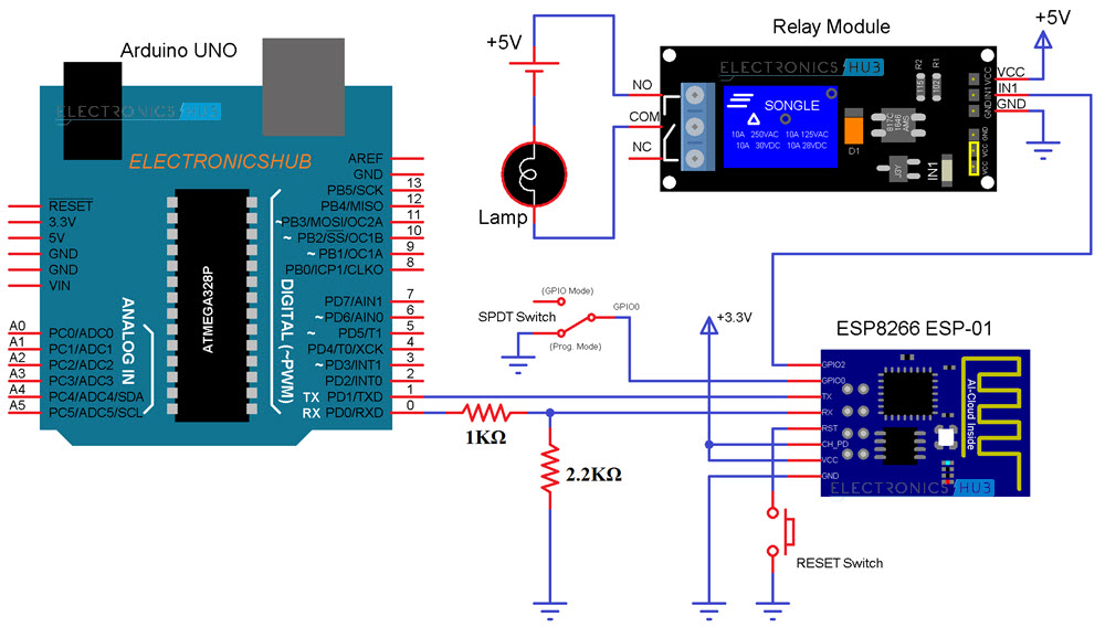
In order to control a relay from anywhere in the World, you need to make the connections as per the following circuit diagram. Arduino is not mandatory as it is used just to program the ESP8266 Module i.e. it is acting as an USB-to-Serial Converter.
If you happen to have a dedicated USB-to-Serial Converter, then you will not need the Arduino Board.
Components Required
- USB-to-Serial Converter (Arduino Board)
- ESP-01 (ESP8266 Module)
- Two Channel Relay Module (only one channel is used)
- Button
- Resistors (1 KΩ and 2.2 KΩ)
- Jumper Wires
- Slide Switch (SPDT)
Circuit Design
The design of the circuit for controlling a relay from anywhere in the World is very simple. In fact, the design is similar to what we made in the ANDROID APP CONTROLLED RELAY PROJECT.
So, I wouldn’t go into the details of the circuit once again and I suggest you to refer to that project for detailed circuit design.
Code
The code for the project is given below. This code is inspired from the aREST example “ESP8266_cloud”. I’ll explain more about in the Working section.
Hardware and Software Configuration
Let us now try to understand the project and see how to control a relay from anywhere in the World using ESP8266.
First, make all the necessary connections as per the circuit diagram. Connect the Arduino to the computer and connect the GPIO0 to GND and reset the ESP Module. Before uploading the code given above, you need to make a few additions and changes.
The first important thing is you need to special libraries called “aREST” and “PubSubClient”. Both these libraries can be downloaded from the following links aREST and PubSubClient.
Download the zip files and extract the contents. Then copy both the folders called “aREST-master” and “pubsubclient-master” to Documents–>Arduino–>libraries. The path will be something like this “C:\Users\Ravi\Documents\Arduino\libraries”.
After doing this, copy the above code into the Arduino IDE and move to the line that says “char* device_id = “re1403”;”. This line contains the unique Device ID specific to your device. Replace this with your ID with a maximum of 6 characters (can be alphanumeric, not sure about special characters).
NOTE: Do not forget to replace “re1403” with your own Device ID.
Once you have assigned the Device ID, move on to the next line and enter your WiFi Network details i.e. SSID and Password. Then move to line that says “arestVar.set_name(“MyESP”);”. Here, you can set a name to your device. This name will be visible once you connect to the aREST Dashboard.
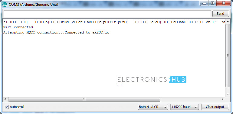
Now you can upload the code to the ESP Module. After uploading, if you open the serial monitor, you can see the status whether the ESP Module is connected to the aREST framework or not.
Control a Relay from anywhere in the World using ESP8266 and a Web Browser
Let us now see the implementation of the project. Remember that, in the circuit, I have connected the Relay Module to the GPIO2 of the ESP Module.
After uploading the code and getting connected to the aREST Server, open a web browser connected to a different network than the ESP8266 Module and enter the following URL.
Using this URL, you are configuring the device with id “re1403” and setting its pin 2 as output. If the configuration is successful, you will get a response as following.
Now, that your device is configured, you can go ahead and control its pins i.e. you can make the pin HIGH or LOW. For that, you need to use two URLs.
To make the pin HIGH, use the following URL.
The response to making the Pin HIGH is as follows.
And to make the pin LOW, the URL is:
The response to this URL is:
{“message”:”Pin D2 set to 0″,”id”:”re1403″,”name”:”MyESP”,”hardware”:”esp8266″,”connected”:true}
NOTE: The relay module, which I have used in the project is an active LOW one. So, a LOW on the ESP will turn ON the relay and a HIGH on the ESP will turn the relay OFF.
That’s it. You can follow all the above mentioned steps and control a relay from anywhere in the World using ESP8266 and aREST.
Control a Relay from anywhere in the world using ESP8266 and aREST Dashboard
Note that you do not need an account in the aREST Framework in order to implement the above mentioned process. But there is an advantage of creating an account with aREST.
Use the following URL and create an account in the aREST.
If you already have an account with aREST, login with your credentials using the above mentioned URL. After this, you will get the following page.
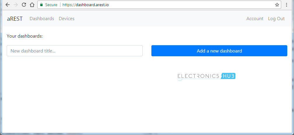
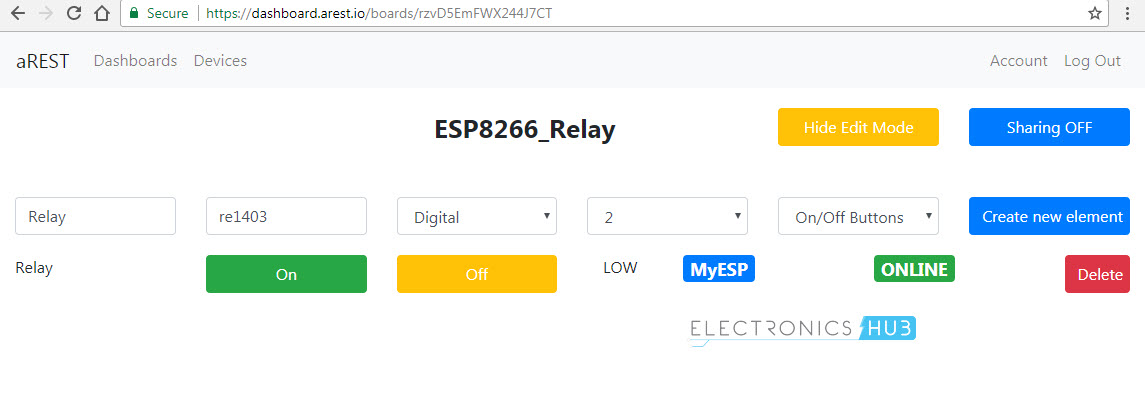
After this, enter a new dashboard title like “ESP8266_Relay” and click on “Add a new dashboard”. This will be added under “Your Dashboards:”. Open the newly created dashboard.
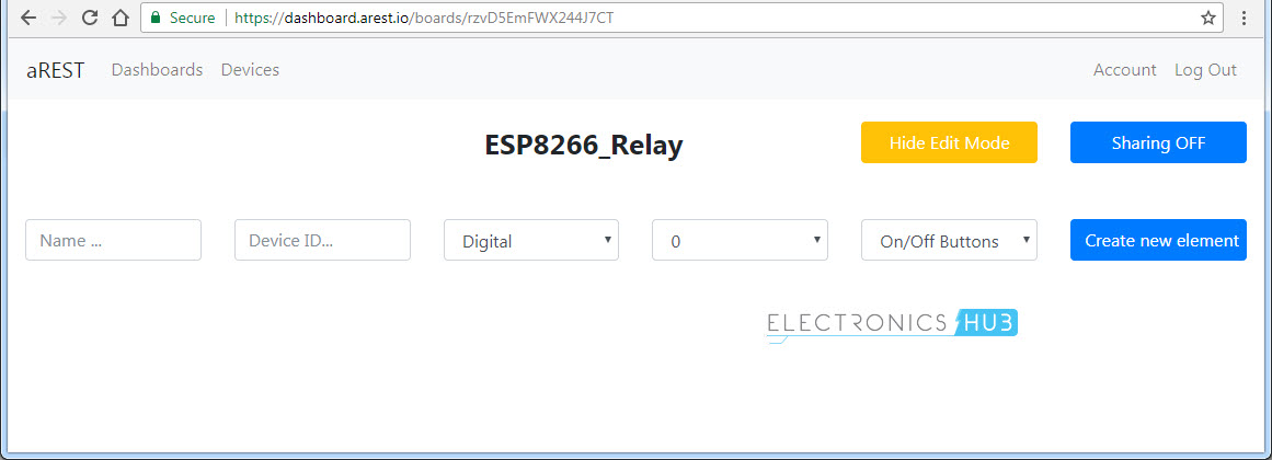
Here, you can add the device you want to control. Give a name to the Device, the Device ID (which you have mentioned in the program), type of Pin (Digital in our case), Pin number (Pin 2) and the type of control (ON – OFF Buttons) and create a new element.
NOTE: You can show or hide the edit details anytime.
If everything goes well, the moment you click on create a new element (with all the details), you will get the name of device, which you set in the code (in my case, it is MyESP) and the status of it (ONLINE).
Now you can control the relay, which is connected to the GPIO2 of the ESP8266 through this interface. So, the benefit of creating an aREST account is that you need not enter the before mentioned URLs to control the ESP Module.
Control a Relay from anywhere in the World using ESP8266 and Android App
In addition to the URL and aREST Dashboard control of the ESP Module, I’ll show you how to create an Android App using MIT App Inventor 2 Application and Control a Relay from anywhere in the World using that app.
All you need is to create two Button elements in the App and a Web element as shown in the image below. I’ve added a few extra labels to mention the title of the project and also indicate the status of the relay.
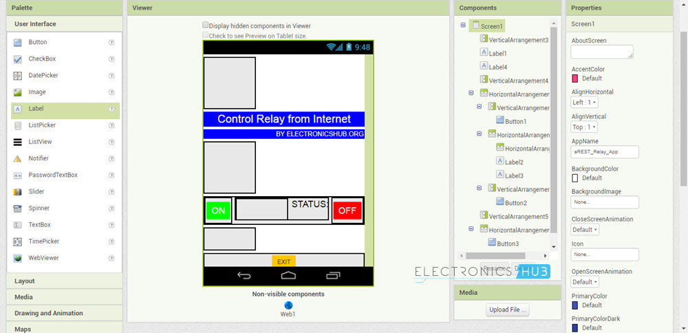
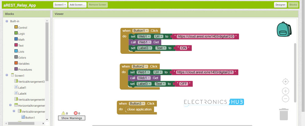
In the blocks section, create blocks for the Buttons and add the Web elements. Link those corresponding web elements to the URLs that I have mentioned earlier. So, when ever you click on the button, the app sends a request to that URL and as a result, controls the relay.
NOTE: I haven’t given the complete details of creating an Android App using the MIT App Inventor 2 Application. If you are interested, I can make a dedicated project on that topic as well.
Applications
- I think the applications of controlling a Relay and as a result an electrical appliance from the internet are very clear.
- A true IOT based Home Automation is one of the main and important application where you can monitor your home essentials like temperature, smoke alarm, etc. and at the same time control any electrical appliances, everything over the internet and from anywhere in the World.

18 Responses
Make video on this project.
Yes. We will make it and upload it as early as possible.
Wonderful. Agree to create a video for a better explanation on how to do it. Good efforts.
What are the costs estimate of this project. It looks something I can try out.
I think somewhere around $35-40.
Wonderful work with good explanations, we really appreciate the efforts u put in, thanks
hi how can we recive massages from the esp to app?
first of all thanks sir.it is very good project .you explanation is very simple to understand the hole project.
and next thing we can control home appliances anywhere in the world for iot enabled room.it is very useful in present technology.Everybody busy in their works forget to off the switches by using app we can switch off the switches anywhere in the world.
my question is how you know present status of your iot enabled room.(how many switches are on and off)
i.e possible should get notification to app how it is done by using mit app inventor could you please explain sir,
waiting for your response
If you have made a video can you post a link
I am using Arduino Nano and I have a problem with the code
ERROR compiling for board Arduino Nano
Can you help?
This code must be directly uploaded to the ESP8266 Module. It won’t work with Arduino (UNO or Nano).
Hi,
I can config the Arduino like AP for take the local wifi “SSID” “PASSWORD” data?.
Best Regards
Thank you so much sir. please provide us with the video link if it is ready.
God bless you more
how to upload Code Error ?
a very nice project ,could you make a video how to make an app so that we can make it.
I have been able to run the code exactly the way you have created. But, i wanted to have multiple device controlled through relay irrespective of the device. I can ON or OFF multiple device.
As i see in the current schematic diagram, if i connect multiple device it will be all ON or all OFF. Can you explain me how to achieve this?
thanks this is a good tutrial and not perfect becauase not mentiones in security in project how i can set high security in web and android app? thanks again
I;m getting below error:
‘class aREST’ has no member named ‘get_topic’
char* out_topic = arestVar.get_topic();
^
exit status 1
‘class aREST’ has no member named ‘get_topic’