In this project, I will discuss about DS3231 RTC Module, important components and features of this module and finally show you how to Interface a DS3231 Real Time Clock (RTC) Module with Arduino.
Outline
ToggleIntroduction
Real Time Clock or RTC is a timekeeping device in the form of an Integrated Circuit or IC. RTC is an integral component of many time critical applications and devices like Servers, GPS, Data Loggers etc.
I have already implemented a couple of projects using Real Time Clock or RTC Module earlier with both 8051 Microcontroller and Arduino.
With 8051, I have used DS1307 RTC Module in a project called RFID BASED CAR PARKING SYSTEM. Coming to Arduino, I have used the same DS1307 RTC in ARDUINO ALARM CLOCK and ARDUINO REAL TIME CLOCK TUTORIAL USING DS1307. If you want a quick reference, you can go through the provided links.
Also, in the Arduino Real Time Clock Tutorial using DS1307 project, I have talked about the need for an RTC. So, I won’t go into that aspect again. I will directly jump into the IC of interest: the DS3231 RTC IC.
A Brief Note on DS3231 RTC IC
The DS3231 is an RTC IC developed by Maxim Integrated. It is a low cost, extremely accurate RTC IC with communication over I2C Interface. An interesting feature of DS3231 RTC IC is that it has integrated crystal oscillator and temperature sensor and hence you don’t have to connect an external crystal.
It is available in SO-16 Package. Although it needs only 8 pins in the available 16 pins to function, the integration of crystal makes the IC bulkier and hence it is packed as a 16-pin IC instead of 8-pin IC.
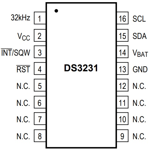
The following image shows the Pin diagram of the DS3231 RTC IC.
Pin Description of DS3231 IC
Coming to the pin description of DS3231 IC, the following table gives a simple functionality overview of the pins.
|
Pin Number |
Pin Name |
Description |
|
1 |
32KHz |
32KHz output |
| 2 | VCC |
DC Power Pin |
|
3 |
INT/SQW | Active LOW Interrupt or Square wave output |
| 4 | RST |
Active LOW Reset |
|
5 – 12 |
NC | No Connection |
|
13 |
GND |
Ground |
| 14 | VBAT |
Back-up Power Supply Input from Battery |
|
15 |
SDA |
Serial Data I/O |
|
16 |
SCL |
Serial Clock Input |
NOTE: Pins 5-12 are NC Pins. They can be tied to GND.
DS3231 RTC Module
Using DS3231 IC as the main component, several manufacturers developed DS3231 RTC Modules with all the necessary components. Almost all the modules available today consists of an additional IC, 24C32N (or something similar). This secondary IC is an EEPROM IC of 32Kb size.
Since both RTC and EEPROM ICs are interfaced through I2C Protocol, you won’t need any extra pins as both these I2C Devices can act as slaves while a microcontroller acts as a master.
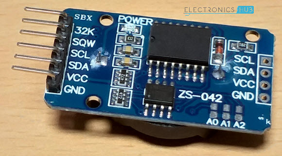
The DS3231 RTC Module used in this project is shown in the image below.
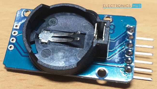
Since RTC is all about maintaining time irrespective of the power supply, you can connect a 3V CR2032 Lithium Battery to the RTC IC to keep the clock ticking. In the DS3231 Module, there is a provision for you to connect a battery using the battery holder provided on the back.
Components and Pin of DS3231 RTC Module
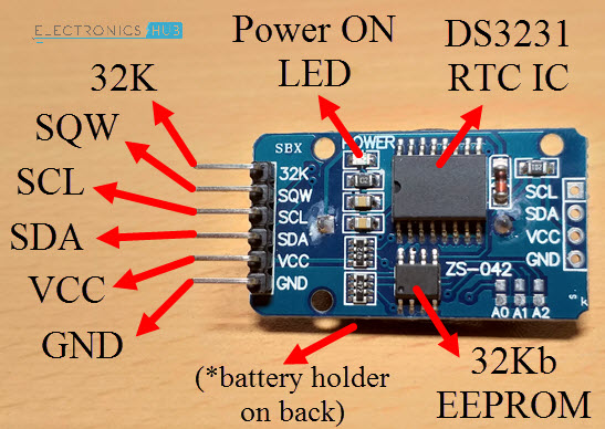
As mentioned earlier, DS3231 IC and 24C32 EEPROM IC are the main components on a typical DS3231 RTC Module board. Apart from that, there are a few other components like Power ON LED, few resistors, capacitors, a battery holder and pins for connecting with microcontroller.
The following image shows the components and pins on the DS3231 RTC Module.
Interfacing DS3231 RTC Module with Arduino
If you remember an earlier project using MicroSD Card Adapter, I have setup a simple data logging application where the data from a sensor is captured and stored in the microSD Card in the form of a text file.
By integrating a Real Time Clock like DS3231 to the above project, you can keep track of the data log with accurate time details.
Hence, interfacing DS3231 RTC Module with Arduino has a numerous application and advantages.
Circuit Diagram
Components Required
- Arduino UNO
- DS3231 RTC Module
- 16×2 LCD Display
- Mini Breadboard
- 10KΩ POT
- Connecting Wires
Circuit Design
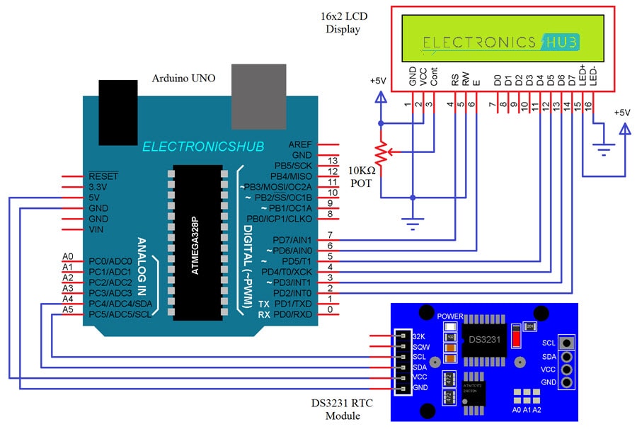
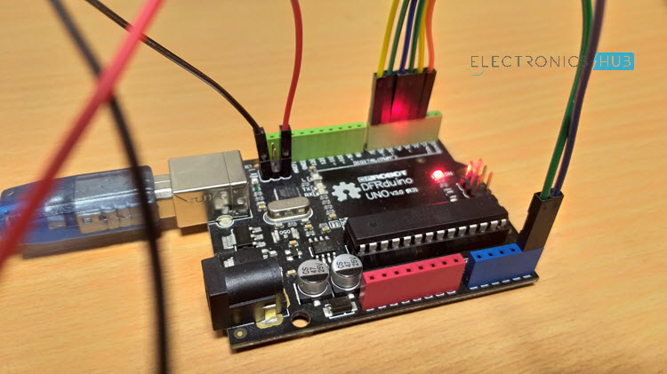
First, let me begin the connections between Arduino and DS3231. Since the interface between them is I2C, identify the I2C Pins on your Arduino Board (if you are using any other board than UNO).
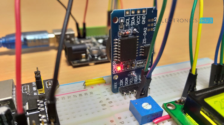
In Arduino UNO, A4 and A5 are SDA and SCL pins. Connect these pins with corresponding SDA and SCL pins of the DS3231 Module. Also, connect the VCC and GND of the RTC Module to +5V and GND of Arduino.
To view the output, I have used an LCD Module. Connect the RS and E pins of LCD to Pins 7 and 6. Connect D4-D7 of LCD to 5-2 of Arduino.
Code
I have used a special library called “RTClib” from Adafruit (which is a forked version of JeeLab’s RTC Library). Download the library from this link and place the extracted folder in the libraries directory of Arduino.
Since the communication is I2C, I have also used the “Wire” library. You don’t need to download this library as it is integrated with Arduino IDE.
Working
The working of the Arduino DS3231 RTC Module Interface is very easy. Arduino first initializes the RTC Module with its slave address (0x68 for DS3231 IC).
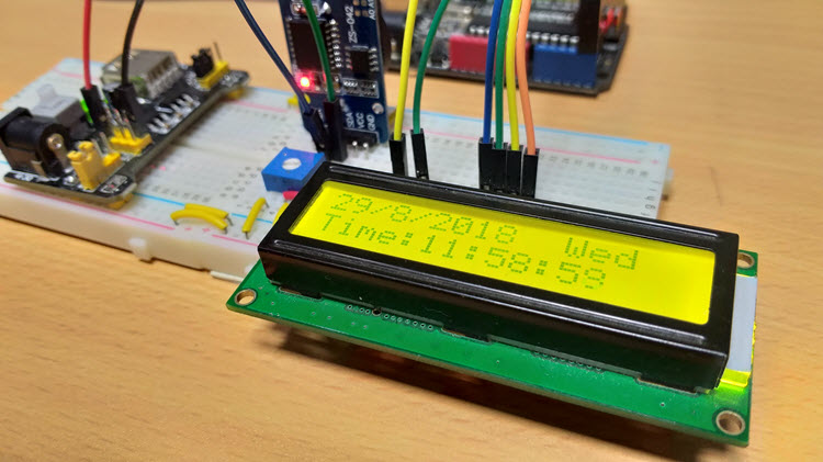
Arduino then updates the internal registers of the RTC IC with the date and time at which the code is compiled and uploaded to Arduino. The uploaded date and time can be viewed on the LCD display.
If you want the DS3231 Module to keep time even after you disconnect power to Arduino, you can connect a 3V Lithium Battery.
Applications
- Servers
- Data Loggers
- GPS Modules
- Power Meters


3 Responses
I’ve teached at vocational high school. With the arduino-uno using, trying to work. I have problems making code in the skech window.
Thanks a lot.
i try to run this code, but it has error. Finally i realize there is wire.begin(); missing in void setup. i added up wire.begin(); in void setup and finally i can export compiled binary for proteus simulation. and it shows exact output 🙂
wire.begin(); is missing in void setup. try add it up at given codes. i’ve just found out what was missing as it shows some error.