In this project, we will learn about the MCP2515 CAN Controller Module, how to interface the MCP2515 CAN Bus Controller with Arduino and finally how to enable communication between two Arduino board with the help of two MCP2515 CAN Controllers and the CAN Protocol.
Outline
ToggleIntroduction
Controlled Area Network of simple CAN is a bus standard that allows a Microcontroller and its peripheral devices to communicate without the need of a host device or a computer.
Developed by Robert Bosch GmbH, CAN is protocol is main used in automobiles for communication between a control unit and its components.
For example, the Engine Control Unit is a major control using in a car. This unit is connected to many sensors and actuators like air flow, pressure, temperature, valve control, motors for air control etc. The communication between these modules and the control unit is through CAN Bus.
In order to understand a little bit more about CAN Bus, CAN Controller and other important aspects, the MCP2515 CAN Bus Controller Module is very helpful.
Also read: BASICS OF SPI COMMUNICATION.
A Brief Note on MCP2515 CAN Bus Controller Module
The MCP2515 CAN Bus Controller is a simple Module that supports CAN Protocol version 2.0B and can be used for communication at 1Mbps. In order to setup a complete communication system, you will need two CAN Bus Module.
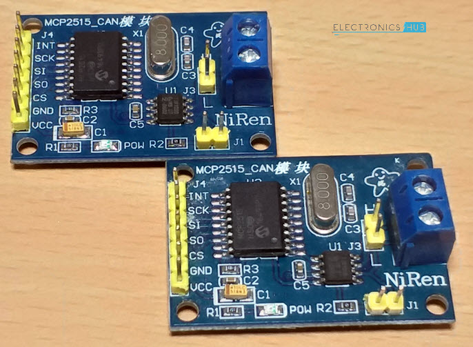
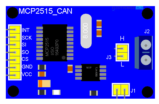
The module used in the project is shown in the image below.
This particular module is based on MCP2515 CAN Controller IC and TJA1050 CAN Transceiver IC. The MCP2515 IC is a standalone CAN Controller and has integrated SPI Interface for communication with microcontrollers.
Coming to the TJA1050 IC, it acts as an interface between the MCP2515 CAN Controller IC and the Physical CAN Bus.
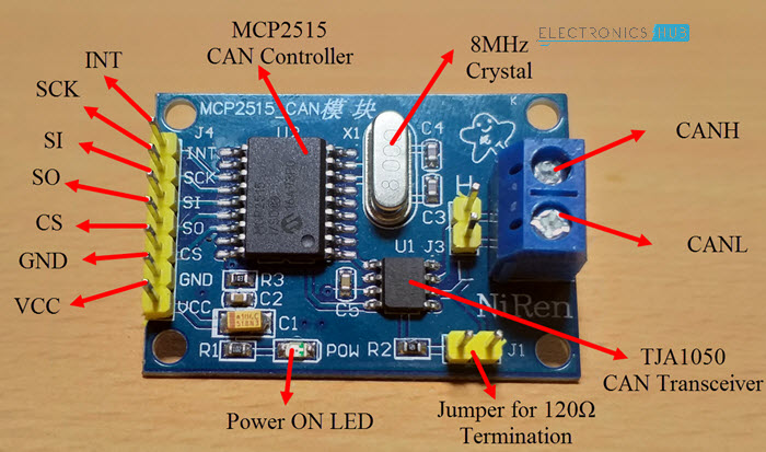
The following image shows the components and pins on a typical MCP2515 Module.
Schematic of MCP2515 CAN Bus Module
Before seeing the schematic of the module, you need to understand a couple of things about both the ICs i.e. MCP2515 and TJA1050.
MCP2515 IC is the main controller that internally consists of three main subcomponents: The CAN Module, the Control Logic and the SPI Block.
CAN Module is responsible for transmitting and receiving messages on the CAN Bus. Control Logic handles the setup and operation of the MCP2515 by interfacing all the blocks. The SPI Block is responsible for the SPI Communication interface.
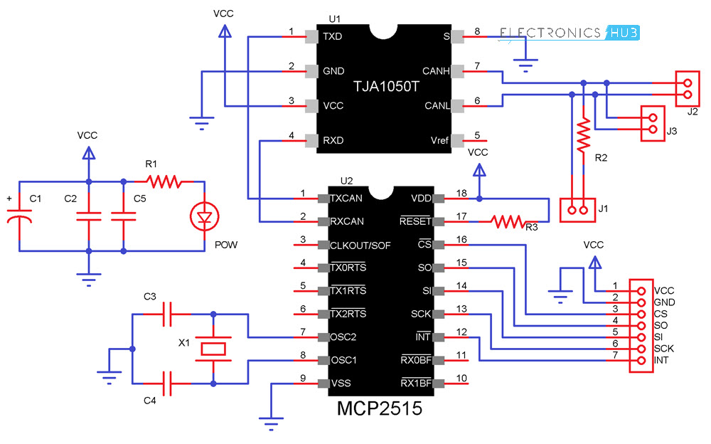
Coming to the TJA1050 IC, since it acts as an interface between MCP2515 CAN Controller and the physical CAN Bus, this IC is responsible for taking the data from the controller and relaying it on to the bus.
The following image shows the schematic of the MCP2515 CAN Module and it shows how MCP2515 IC and TJA1050 IC are connected on the Module.
Circuit Diagram for Interfacing MCP2515 with Arduino
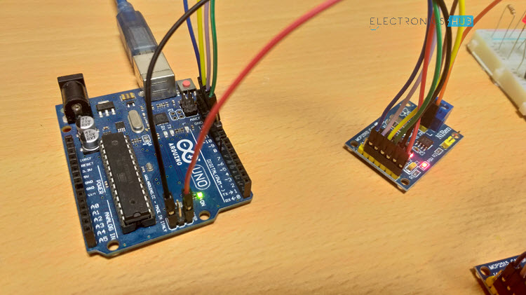
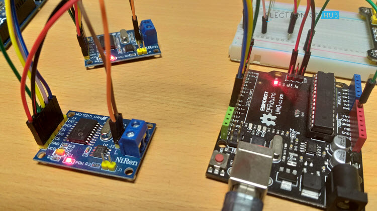
The following image shows the circuit diagram of interfacing MCP2515 CAN Module with Arduino and possible communication between two Arduino over CAN Protocol.
If the pins of the MCP2515 Module are not clear, the following image might be useful.
Components Required
- Arduino UNO x 2 [Buy Here]
- MCP2515 x 2
- USB Cable x 2
- Connecting Wires
Circuit Design
As mentioned earlier, the CAN Controller IC facilitates SPI Communication Protocol for interfacing with any Microcontroller. Hence, connect the SPI Pin i.e. SCK, MOSI (SI), MISO (SO) and CS of the MCP2515 Module to corresponding SPI Pins of Arduino (see circuit diagram).
Make two such connections: one pair acts as a transmitter and the other as a receiver. Now for the communication between this transmitter and receiver, connect CANH and CANL pins of each MCP2515 Module.
Code
Before going into the code, you need to download a library for the MCP2515 Module. There are many libraries but I have used this particular one.
Download it and place the extracted contents in the libraries directory of Arduino.
Since the communication involves a Transmitter Module and a Receiver Module, the code is also divided into Transmitter Code and Receiver Code.
Transmitter Code
Receiver Code
Working
Working of this project is very simple as all the work is done by the libraries (SPI and CAN). Since CAN is message-based communication, you need to send a message anywhere between 0 and 8 bytes.
In this project, the transmitter is sending a message as 1 1 2 3 0 5 6 7. This message is transmitted over CAN Bus and the receiver receives this message and is displayed on its serial monitor.
Additionally, the 0th and 4th bit i.e. 1 and 0 in the above sequence are extracted separately by the receiver and turns ON and OFF the LED connected to Pin 2 of Arduino.
Applications
As mentioned in the introduction, CAN is widely used in the field of automobiles. Some of the applications include:
- Electronic Gear Shift System
- Main Interface in Automation (like industrial)
- Medical Equipment
- Robotics
- Auto Start/Stop of Car Engine



18 Responses
Thank you for the information. Getting 2 Arduinos+MCP talking to each other is interesting and simple. The challenge happens when you connect to the OBDII port of a vehicle. That’s when according to my experience, things get a lot more complicated:
– Vehicles can use standard CAN frames or extended ones (I’m not quite sure the Seeed library works with extended CAN frames).
– Even with vehicles that use standard CAN frames, when you send the PID asking for example for the engine’s RPMs, it seems the vehicle doesn’t receive the data.
Any guidance please?
Thanks,
Dave
If you didn’t already find out the answer, most newer cars have firewalls and so you can’t get certain data from the OBD port unless you’re actually using OBD protocols to get DTC PIDs. Older cars with direct connection to the ECU for example should work.
Hey! It seems very nice the example that you shows. I just want to know if I can codify one Arduino as transmitter and receiver at the same time.
Thanks!!
Paula
Hi. I am after something similar to Paula. In my case I am interested in running two CAN modules from the one Arduino – either in a dual-bus car (HSCAN=500kbps, MSCAN=125kbps) or as an isolating CAN bridge – for example, when an Elctro-Hydraulic Power Steering Pump from a different model that needs CAN translation of broadcasts to work but must not see the original messages of the new vehicle. While SPI is fine for multiple modules, I think I am struggling to find a library that supports multiple CAN interfaces at the same time.
Luke
Probably you found this already, but in case you need it:
You can connect to 2 MC2515 shiles by creating 2 different objects like this:
MCP_CAN CAN_ONE(spiCSPin1);
MCP_CAN CAN_TWO(spiCSPin2);
You need two CS pins – for example
spiCSPin1 = 10
spiCSPin2 = 9
You connect these to the corresponding CS pin on each CAN module
and the other SPI pins ( 11,12,13 ) are connected to both modules
SPI is a bus, so you only need 1 additional pin for each slave device.
So, you can initialize the two modules with different spees for CANbus. etc and you can read and write separately.
You may need additional pins if you rely on Interrupt pin to notify you about received messages. In that case you may use pins 2 and 3 . Otherwise you can relay on frequent polling of the 2 modules. However, have in mind also programming is more complicated with 2 modules and the MCU could be overloaded
Hi Paula!
could you solve your issue? I need something like that!
Thanks!
Alexandre
Hello,
My project like this, however I using lm 35 tem. sensor. But I couln’t write code. How can ı write ?
Hi
If I need to send message, then receive an answer, repack answer into different packet and send it back – how to do it in a single sketch?
I’m in a University Project, in wich we build an eletric motorcycle , communication are made with CAN. I have used half of your project to try and read the BUS CAN, but it can´t even pass the begin.CAN loop. From what i have seen in the web it may be due to crystal being a 8oooKhz and the library is made for 16000Khz. Can you help me?
Probably too late for you but someone else might find this useful. The function mcp2515_configRate accepts the crystal frequency as the second parameter….. for 8MHz just pass MCP_8MHz
/*********************************************************************************************************
** Function name: mcp2515_configRate
** Descriptions: set baudrate
*********************************************************************************************************/
byte mcp2515_can::mcp2515_configRate(const byte canSpeed, const byte clock) {
byte set, cfg1, cfg2, cfg3;
set = 1;
switch (clock) {
case (MCP_16MHz) :
switch (canSpeed) {
case (CAN_5KBPS):
cfg1 = MCP_16MHz_5kBPS_CFG1;
cfg2 = MCP_16MHz_5kBPS_CFG2;
cfg3 = MCP_16MHz_5kBPS_CFG3;
break;
case (CAN_10KBPS):
cfg1 = MCP_16MHz_10kBPS_CFG1;
cfg2 = MCP_16MHz_10kBPS_CFG2;
cfg3 = MCP_16MHz_10kBPS_CFG3;
break;
case (CAN_20KBPS):
cfg1 = MCP_16MHz_20kBPS_CFG1;
cfg2 = MCP_16MHz_20kBPS_CFG2;
cfg3 = MCP_16MHz_20kBPS_CFG3;
break;
case (CAN_25KBPS):
cfg1 = MCP_16MHz_25kBPS_CFG1;
cfg2 = MCP_16MHz_25kBPS_CFG2;
cfg3 = MCP_16MHz_25kBPS_CFG3;
break;
case (CAN_31K25BPS):
cfg1 = MCP_16MHz_31k25BPS_CFG1;
cfg2 = MCP_16MHz_31k25BPS_CFG2;
cfg3 = MCP_16MHz_31k25BPS_CFG3;
break;
case (CAN_33KBPS):
cfg1 = MCP_16MHz_33kBPS_CFG1;
cfg2 = MCP_16MHz_33kBPS_CFG2;
cfg3 = MCP_16MHz_33kBPS_CFG3;
break;
case (CAN_40KBPS):
cfg1 = MCP_16MHz_40kBPS_CFG1;
cfg2 = MCP_16MHz_40kBPS_CFG2;
cfg3 = MCP_16MHz_40kBPS_CFG3;
break;
case (CAN_50KBPS):
cfg1 = MCP_16MHz_50kBPS_CFG1;
cfg2 = MCP_16MHz_50kBPS_CFG2;
cfg3 = MCP_16MHz_50kBPS_CFG3;
break;
case (CAN_80KBPS):
cfg1 = MCP_16MHz_80kBPS_CFG1;
cfg2 = MCP_16MHz_80kBPS_CFG2;
cfg3 = MCP_16MHz_80kBPS_CFG3;
break;
case (CAN_83K3BPS):
cfg1 = MCP_16MHz_83k3BPS_CFG1;
cfg2 = MCP_16MHz_83k3BPS_CFG2;
cfg3 = MCP_16MHz_83k3BPS_CFG3;
break;
case (CAN_95KBPS):
cfg1 = MCP_16MHz_95kBPS_CFG1;
cfg2 = MCP_16MHz_95kBPS_CFG2;
cfg3 = MCP_16MHz_95kBPS_CFG3;
break;
case (CAN_100KBPS):
cfg1 = MCP_16MHz_100kBPS_CFG1;
cfg2 = MCP_16MHz_100kBPS_CFG2;
cfg3 = MCP_16MHz_100kBPS_CFG3;
break;
case (CAN_125KBPS):
cfg1 = MCP_16MHz_125kBPS_CFG1;
cfg2 = MCP_16MHz_125kBPS_CFG2;
cfg3 = MCP_16MHz_125kBPS_CFG3;
break;
case (CAN_200KBPS):
cfg1 = MCP_16MHz_200kBPS_CFG1;
cfg2 = MCP_16MHz_200kBPS_CFG2;
cfg3 = MCP_16MHz_200kBPS_CFG3;
break;
case (CAN_250KBPS):
cfg1 = MCP_16MHz_250kBPS_CFG1;
cfg2 = MCP_16MHz_250kBPS_CFG2;
cfg3 = MCP_16MHz_250kBPS_CFG3;
break;
case (CAN_500KBPS):
cfg1 = MCP_16MHz_500kBPS_CFG1;
cfg2 = MCP_16MHz_500kBPS_CFG2;
cfg3 = MCP_16MHz_500kBPS_CFG3;
break;
case (CAN_666KBPS):
cfg1 = MCP_16MHz_666kBPS_CFG1;
cfg2 = MCP_16MHz_666kBPS_CFG2;
cfg3 = MCP_16MHz_666kBPS_CFG3;
break;
case (CAN_1000KBPS):
cfg1 = MCP_16MHz_1000kBPS_CFG1;
cfg2 = MCP_16MHz_1000kBPS_CFG2;
cfg3 = MCP_16MHz_1000kBPS_CFG3;
break;
default:
set = 0;
break;
}
break;
case (MCP_8MHz) :
switch (canSpeed) {
case (CAN_5KBPS) :
cfg1 = MCP_8MHz_5kBPS_CFG1;
cfg2 = MCP_8MHz_5kBPS_CFG2;
cfg3 = MCP_8MHz_5kBPS_CFG3;
break;
case (CAN_10KBPS) :
cfg1 = MCP_8MHz_10kBPS_CFG1;
cfg2 = MCP_8MHz_10kBPS_CFG2;
cfg3 = MCP_8MHz_10kBPS_CFG3;
break;
case (CAN_20KBPS) :
cfg1 = MCP_8MHz_20kBPS_CFG1;
cfg2 = MCP_8MHz_20kBPS_CFG2;
cfg3 = MCP_8MHz_20kBPS_CFG3;
break;
case (CAN_31K25BPS) :
cfg1 = MCP_8MHz_31k25BPS_CFG1;
cfg2 = MCP_8MHz_31k25BPS_CFG2;
cfg3 = MCP_8MHz_31k25BPS_CFG3;
break;
case (CAN_40KBPS) :
cfg1 = MCP_8MHz_40kBPS_CFG1;
cfg2 = MCP_8MHz_40kBPS_CFG2;
cfg3 = MCP_8MHz_40kBPS_CFG3;
break;
case (CAN_50KBPS) :
cfg1 = MCP_8MHz_50kBPS_CFG1;
cfg2 = MCP_8MHz_50kBPS_CFG2;
cfg3 = MCP_8MHz_50kBPS_CFG3;
break;
case (CAN_80KBPS) :
cfg1 = MCP_8MHz_80kBPS_CFG1;
cfg2 = MCP_8MHz_80kBPS_CFG2;
cfg3 = MCP_8MHz_80kBPS_CFG3;
break;
case (CAN_100KBPS) :
cfg1 = MCP_8MHz_100kBPS_CFG1;
cfg2 = MCP_8MHz_100kBPS_CFG2;
cfg3 = MCP_8MHz_100kBPS_CFG3;
break;
case (CAN_125KBPS) :
cfg1 = MCP_8MHz_125kBPS_CFG1;
cfg2 = MCP_8MHz_125kBPS_CFG2;
cfg3 = MCP_8MHz_125kBPS_CFG3;
break;
case (CAN_200KBPS) :
cfg1 = MCP_8MHz_200kBPS_CFG1;
cfg2 = MCP_8MHz_200kBPS_CFG2;
cfg3 = MCP_8MHz_200kBPS_CFG3;
break;
case (CAN_250KBPS) :
cfg1 = MCP_8MHz_250kBPS_CFG1;
cfg2 = MCP_8MHz_250kBPS_CFG2;
cfg3 = MCP_8MHz_250kBPS_CFG3;
break;
case (CAN_500KBPS) :
cfg1 = MCP_8MHz_500kBPS_CFG1;
cfg2 = MCP_8MHz_500kBPS_CFG2;
cfg3 = MCP_8MHz_500kBPS_CFG3;
break;
case (CAN_1000KBPS) :
cfg1 = MCP_8MHz_1000kBPS_CFG1;
cfg2 = MCP_8MHz_1000kBPS_CFG2;
cfg3 = MCP_8MHz_1000kBPS_CFG3;
break;
default:
set = 0;
break;
}
break;
default:
set = 0;
break;
}
if (set) {
mcp2515_setRegister(MCP_CNF1, cfg1);
mcp2515_setRegister(MCP_CNF2, cfg2);
mcp2515_setRegister(MCP_CNF3, cfg3);
return MCP2515_OK;
} else {
return MCP2515_FAIL;
}
}
Suppose I want to connect 4 Arduino’s via 4 CAN modules.
What’s then the preferred way to send a CAN Message direct to just 1 specific CAN receiver?
It’s not the arduino which has the address, it’s the application. When your specific arduino runs the „application“ with a fix Id, you can address that.
So you need to design your application about the messages which you wand to send. E.g.: turn lamp on, ID 0x45, turn off lamp ID 0x46. Turn on horn, 0x10 – send every 10ms if not horn turns off. In a Car normally you send every X ms a message to tun on a front light if the message is not send, the lamp turn off. It depends on the security function of your application.
Hi,
I have copied the exact code for transmitter and receiver Code, and downloaded the related libraries for as mentioned above.
However, while compiling error message ‘cannot declare variable CAN to be of abstract type MCP_CAN’
Can anyone help me in resolving this error
Hi,
Did you find out the solution?
I have the same error 🙁
Could you share how to fix it?
I found the solution in the examples.
#include
#include “mcp2518fd_can.h”
const int SPI_CS_PIN = 9;
mcp2515_can CAN(SPI_CS_PIN); // Set CS pin
It works now.
Can you please share the code. actually, I’m doing something similar to it.
I am trying to communicate the CAN messages from a battery. so i just need to have the receiver side of code. but its not working. its just displaying the same value every-time.
Can you please help me out.
Does this support python programing ?
Hi, can anyone help me and let me know what modifications I need to do in order to allow this to work with arduino mega?
I have tried using the same pins and same code, but keep getting the message
“CAN BUS init Failed”
Thanks,
Tom