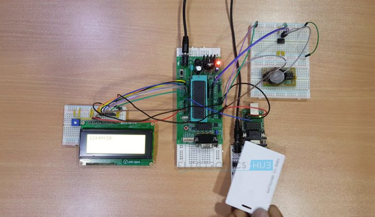
RFID based Car Parking System is a simple project that offers an efficient car parking management system with the help of RFID Technology.
Car parking management in organisations and malls often consists of many tasks like issuing tokens, noting the check-in and check-out time, calculating fare and finally collecting the amount.
As the number of vehicles are increasing, the problems faced by manual parking management system are also increasing. Such problems can be eliminated to some extent by implementing an intelligent parking system where the entry and exit of cars is monitored and payment is made easy with sensor technology.
This project deals with an interesting manner of security access based car parking system using AT89C51 microcontroller and RFID Technology.
Principle of RFID based Car Parking System
The principle of operation of the project lies in functioning of RFID, RTC and EEPROM.
RFID Card is specific to the user and the card details are pre-programmed in the microcontroller. When the RFID card is swiped against the RFID Reader, it gets energised from the reader and sends the information to the reader.
The reader then transmits the card’s information to the microcontroller via serial communication protocol.
The microcontroller then checks for the received card details with already stored details and checks for authenticity of the card.
If the card is existing in the database, the microcontroller will check for the current time in the RTC module and stores the in time details of the particular card in the EEPROM.
The communication between the microcontroller and RTC module is using I2C protocol. The communication between the microcontroller and the EEPROM is also using I2C protocol.
If the card is swiped again, the in time details from the EEPROM and out time details from the RTC are taken and the fare is calculated as per the tariffs.
Circuit Diagram
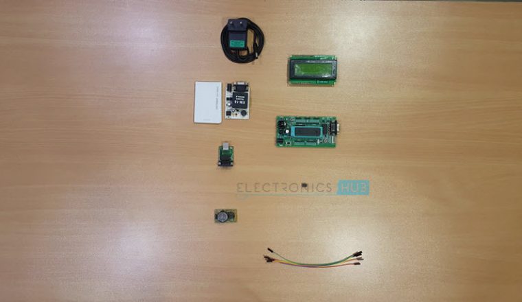
Components
Complete project tutorial with CODE: RFID based Car Parking System
Component Description
DS1307 RTC
A Real time clock or RTC, as the name indicates, is a clock module in the form of an IC, which keeps track of the current time. RTCs are present in almost all electronic devices like personal computers, servers, and embedded systems, which need to keep accurate time.
The main advantage of RTC is that they run on battery and keeps the clock and calendar running even if there is a power failure.
The Real Time Clock used in this project is DS1307.
EEPROM (24C04 – 4K)
- EEPROM stands for Electrically Erasable Programmable Read Only Memory. It is a type of non-volatile memory i.e. it can hold the data even when the power is removed and the data can be electrically erased and reprogrammed.
- EEPROMs are used in electronic devices to store small amounts of data.
- The EEPROM used in this project is 24C04 which has a memory of 4 KB.
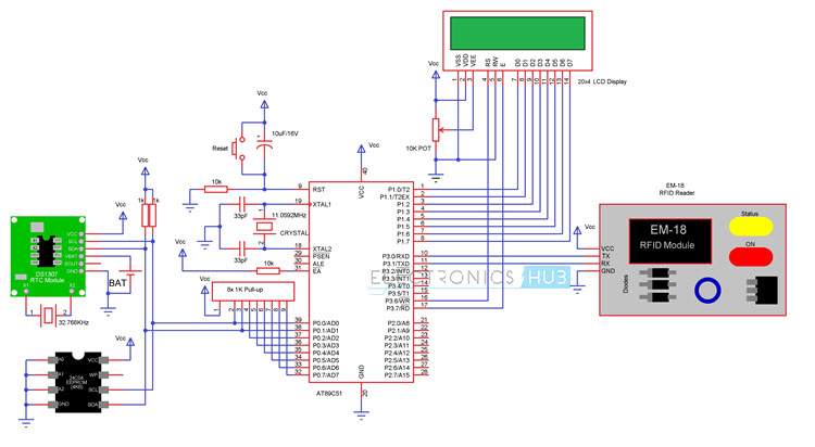
Circuit Design
The main connections for basic functioning of the microcontroller include a reset circuit, oscillator circuit and EA Pin. Reset circuit consists of a push button, 10KΩ resistor and a 10µF capacitor.
External oscillator circuit consists of an 11.0592 MHz quartz crystal and two 33pF capacitors. Finally, a 10KΩ resistor is used with EA pin to pull it high.
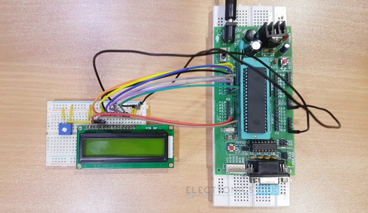
The next hardware we need to connect is the 20 x 4 LCD. The pin configuration of a 20 x 4 LCD is similar to that of a 16 x 2 LCD. The only difference is that a 20 x 4 LCD has few extra segments. In order to access those extra segments, we need to program the microcontroller accordingly.
P3.6, GND and P3.7 pins are connected to the three control pins of the 20 x 4 LCD i.e. RS, RW and E. The data pins of the 20 x 4 LCD are connected to Port 1 of the microcontroller.
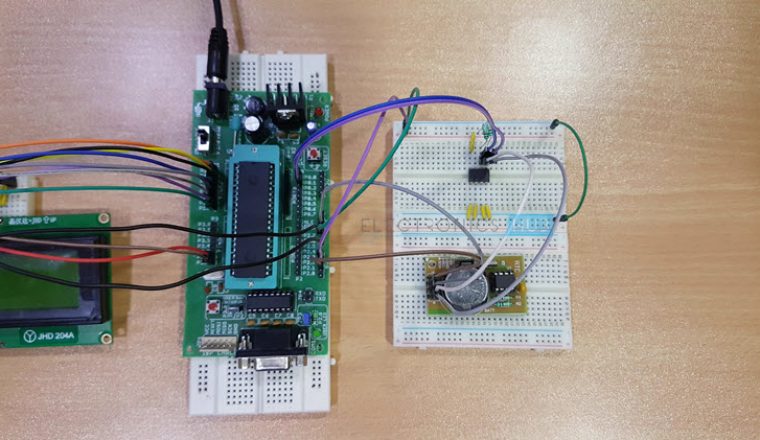
The next component we are going to connect is the RTC. First we have to connect a 32.786 MHz crystal oscillator between the oscillator pins of the RTC IC.
Then connect a 3V coin type Lithium battery to the VBAT terminal of the RTC IC. Finally the I2C terminals i.e. SCL and SDA of the RTC IC are connected to PORT0 pins.
Hence, they must be pulled high with 1K resistors. Now you can connect SCL and SDA to P0.0 and P0.1 of the microcontroller.
After connecting the RTC, now we are going to connect the EEPROM. First connect the SCL and SDA pins of the EEPROM IC to the P0.0 and P0.1 pins of the microcontroller. Then, connect the address input pins of the EEPROM to Ground.
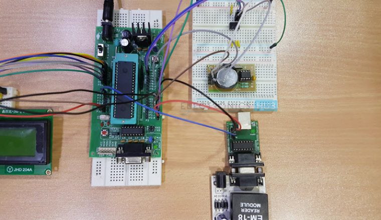
Finally, connect the RFID reader to the controller. Connect the TX pin of the RFID Reader to RXD pin (P3.0 ) of the Controller and RX of RFID is connected to TXD (P3.1) of microcontroller.
“Also read this interesting post: RFID Security Access Control System using 8051
Working
- The project shows the design of an RFID based car parking system using 8051 microcontroller, in which only authorised personnel with valid RFID card are allowed access to park and also the IN/OUT time details along with the fare are automatically calculated.
- When the circuit is switched ON, current time is displayed on the LCD display.
- When the ID card is detected by the reader, a unique card number is sent to the microcontroller.
- If the card number is matched with saved number in microcontroller or database, the microcontroller will allow the car in order to park in the secured area.
- The entry time details of the particular card are stored in the EEPROM. A welcome message along with the in time details are displayed on the LCD.
- When the same card is swiped again, the microcontroller will display the in and out time along with the calculated fare details on the LCD.
Advantages and Applications
- RFID based Car Parking System is implemented in this project and can be used to eliminate the hassle of manual operation of parking system.
- This system can help in reducing cost, increase in productivity and saves time.
- Accurate timing details are measured with the help of RTC Module.
- Prepaid and postpaid cards can be integrated with the system for easy payment options.
Limitations
- Only fare details are calculated but can be extended to credit card or other monetary card system where the fare amount is automatically deducted.
- Further tracking systems like number plate tracking, face tracking etc. can be implemented for accuracy and security.

One Response
hie, how can i get the program code for this project?