

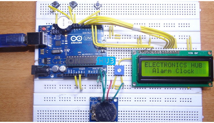
In this project, we designed an Arduino based Real Time Clock with alarm. A Real Time Clock or RTC is a battery powered clock that measures time even when there is no external power or the microcontroller is reprogrammed.
An RTC displays clock and calendar with all timekeeping functions. The battery, which is connected to the RTC is a separate one and is not related or connected to the main power supply.
When the power is restored, RTC displays the real time irrespective of the duration for which the power is off. Such Real Time Clocks are commonly found in computers and are often referred to as just CMOS (Complementary Metal Oxide Semiconductor).
Most microcontrollers and microprocessors have built in timers for keeping time. But they work only when the microcontroller is connected to power supply.
When the power is turned on, the internal timers reset to 0. Hence, a separate RTC chip is included in applications like data loggers for example, which doesn’t reset to 0 when the power is turned off or reset.
Real Time Clocks are often useful in data logging applications, time stamps, alarms, timers, clock builds etc. In this project, a Real Time Clock, which displays accurate time and date along with an alarm feature is designed.
One of the frequently used RTC ICs DS1307 is used in this project along with Arduino. The circuit, design and working are explained in the following sections.
Arduino Alarm Clock
Circuit Diagram
 Components Required
- Arduino UNO – 1 [Buy Here]
- DS 1307 RTC Module – 1
- Push Buttons – 3
- 16X2 LCD Display – 1 [Buy Here]
- Buzzer – 1
- 10 KΩ – 2
- 10 KΩ POT – 1
Component Description
DS1307
DS1307 is the frequently used real time clock (RTC) IC for clock and calendar. The clock function provides seconds, minutes and hours while the calendar function provides day, date, month and year values.
The clock can operate in either 12 hour with AM/PM indication or 24 hour format. A 3V backup battery must be connected to the RTC so that the IC can automatically switch to the backup supply in case of power failure. A
32.768 KHz crystal is connected to the oscillator terminal of DS1307 for 1 Hz oscillations.
Circuit Design
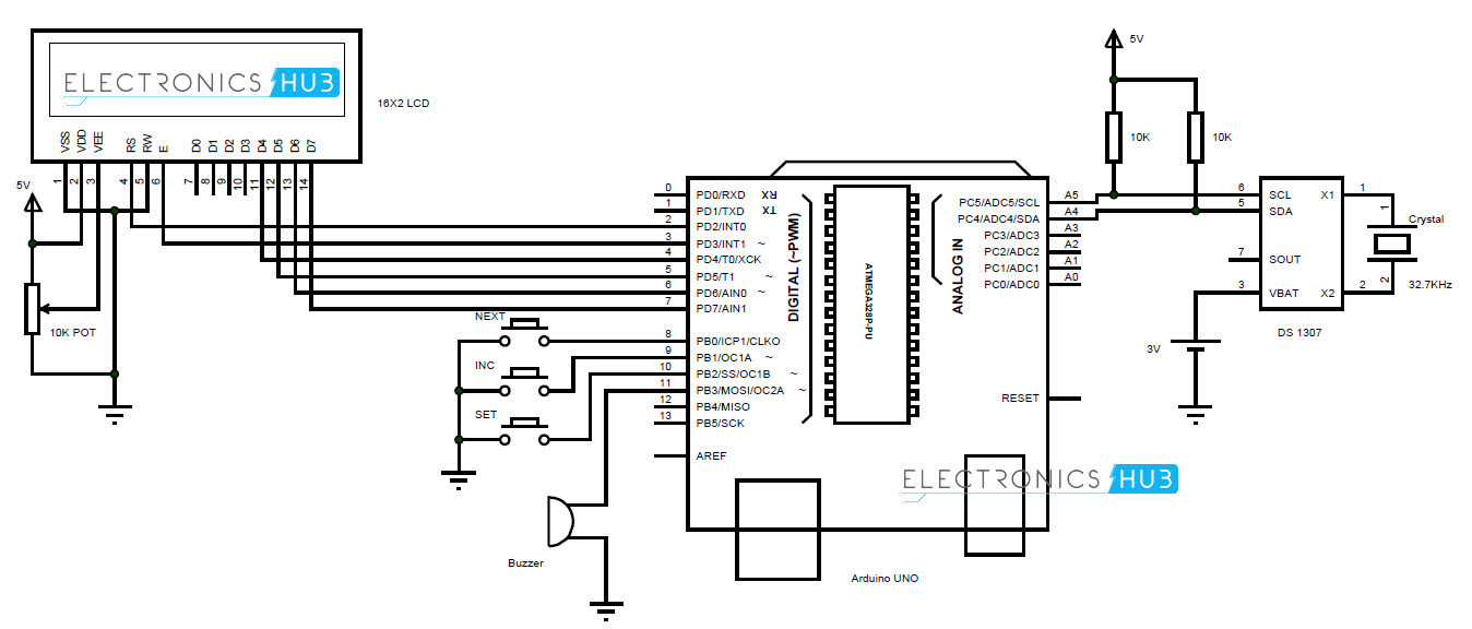
The communication between microcontroller and RTC IC DS1307 is serial I2C bidirectional bus. I2C protocol is a method of communication between a faster device (Microcontroller or Arduino in this case) in master mode and a slower device (RTC) in slave mode.
There are two pins on Arduino for I2C communication. Analog pins 4 and 5 will act as SDA (Serial Data) and SCL (Serial Clock).
These are connected to respective SDA and SCL pins of RTC. Both these pins of RTC are pulled high using 10KΩ resistors.
An LCD is used to display the clock. 6 pins of LCD must be connected to Arduino. RS, E, D4, D5, D6 and D7 (Pins 4, 6, 11, 12, 13 and 14) of LCD are connected to pins 2, 3, 4, 5, 6 and 7 of Arduino.
Three buttons are used to set the alarm. These buttons are connected to pins 8, 9 and 10 of Arduino. A buzzer is connected to pin 11 of Arduino that acts as an alarm.
Working
The aim of this project is to create a real time clock along with an alarm feature. The working of the project is explained below.
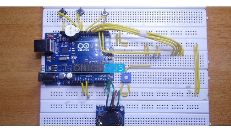
All the connections are made as per the shown circuit diagram. The code for Arduino is uploaded and the LCD displays the current date and time.
In order to set the alarm, we press the set button. It’ll go to alarm mode and asks for hours with current time being displayed. The increment button must be pressed must be pressed to change the hours.
As the clock is in 24 hour format, the hours will be incremented between 0 and 23. Once the hours of the alarm is set, we must press the next button to go to minutes tab.
Again increment button is pressed to change the minutes. Once the alarm time is entered, set button is pressed and the alarm is set.
The values entered as alarm are stored in the EEPROM of the Arduino. These values are continuously compared with the present time.
When the stored values and current value match, the buzzer for the alarm will be triggered. In order to stop the alarm, the next button is pressed.
Output Video
Code
NOTE
- A simple Real Time Clock, which has an alarm feature is designed in this project using Arduino and RTC IC.
- The time and alarm will keep on running as there is a backup supply to the RTC and alarm is stored in the internal EEPROM of Arduino.
- Functions like snooze and multiple alarms can be added by modifying the code of Arduino.
49 Responses
I need circuit diagram.can you send?
Read the post completely..circuit diagram is given
Could you send the code for alarm ?
We will upload it soon..
code please!!
Where is the code?
Please check the aticle
how could i set multiple alarm !????
how could i set multiple alarm ???
i need too . four alarms at least
Sir what is the use of this line int tmp,Inc,hor,mIn,add=11;? is there other button that is connected to pin 11 of arduino maybe?
Pin 11 of Arduino is connected to the Buzzer but it is declared as “#define buz 11”. The “line int tmp,Inc,hor,mIn,add=11;” is declaring some integer variables.
where’s the library?
I’m getting wrong time please help me
Any one help plz i have made this project all circuit is complete when i turn on battery lcd is on but there is no display like no number is displayed. Can anyone sort this out?
Hi, Try to check the connections once again. Adjust the Potentiometer connected to the LCD to vary the contrast.
can u mail me the rtc library used here and how can i set multiple alarms at a time (up to 10 alarms)
The library for RTC Module can be downloaded from here https://github.com/adafruit/RTClib
Can I Make this Using Arduino Mega???
As I borrowed an Arduino Mega module from my senior and don’t want to buy UNO needlessly???
Yes. You can use Arduino Mega for this project.
would you show me the code of alarm?
The code for the project is uploaded in the page. Also, you can download the code from here https://gist.github.com/elktros/c10418217c7348c26760ed9fbb5ff244#file-arduino-alarm-clock
Is this the full working code
How do I set the clock for 12 hours since this watch you are posting in 24 hours? Thank you
Can you add some notes?
Sir ,
Can you send the multi alarm clock’s arduino code. Plzzz…
Can I download the shcematic (Eagle CAD File) of this circuit??