Wireless Communication in any form has become an essential part of human life whether it may be short distance T.V Remote or long distance radio communication. Wireless communication is all about transmission of data wirelessly so that there is no hassle of any wires and no direct contact with the device itself.
One of the easiest and cheapest ways to implement wireless communication is using RF Module (Radio Frequency Module).
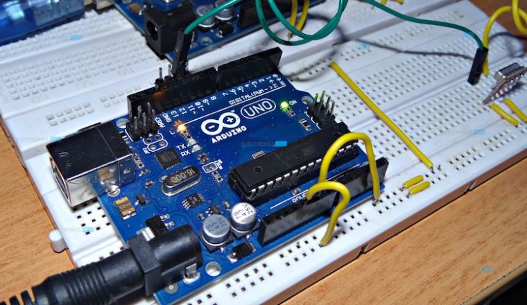
Arduino on the other hand, is a low cost solution for microcontroller applications with open source hardware and software. Arduino can be used in many small to real time applications with simple programming and hardware components.
By combining the two objects i.e. wireless communication with Arduino, we can create a wide range of applications like remote controlled cars, wirelessly operated robots, home automation, simple data transfer etc.
Arduino and RF Transmitter Receiver Module
In this project, we are going to design a system in which two Arduino boards will communicate with each other using RF Module.
Circuit Diagram
As it is a wireless communication project, the circuit consists of a Transmitter part and a Receiver part.
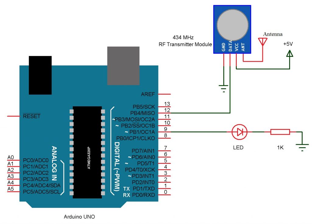
The circuit for the Transmitter part of the project is shown below.
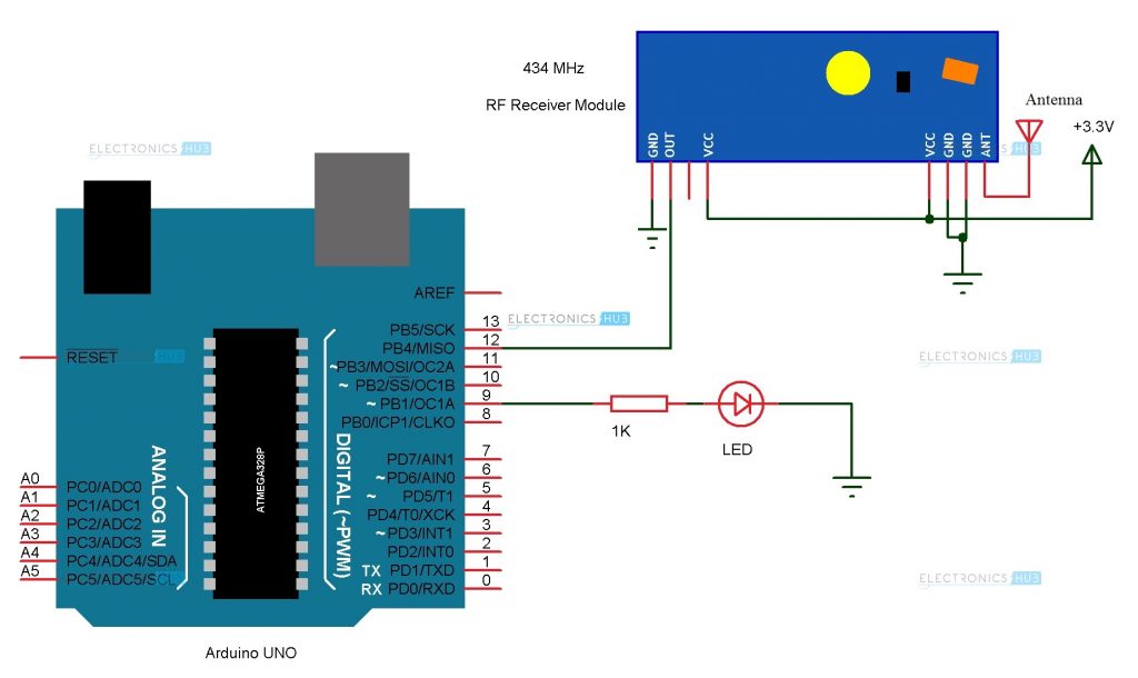
And the circuit for the Receiver part of the project is shown below.
Components Required
Transmitter Part
- Arduino UNO (or any other Arduino board) [Buy Here]
- 434 MHz Transmitter Module (or 315 MHz Module)
- LED [Buy Here]
- 1 KΩ Resistor
- Prototyping board (bread board)
- Connecting wires
- Power supply (Adapter or battery)
Receiver Part
- Arduino UNO (or any other Arduino board) [Buy Here]
- 434 MHz Receiver Module (or 315 MHz Module)
- LED
- 1 KΩ Resistor
- Prototyping board (bread board)
- Connecting wires
- Power supply (adapter or battery)
- RF Module
Component Description
Arduino UNO:
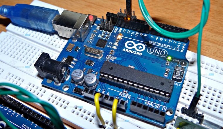
Arduino UNO is the low cost, open source, microcontroller board for electronics prototyping. In this project, two Arduino boards will communicate using wireless communication.
RF Module:
RF Module is a cheap wireless communication module for low cost application. RF Module comprises of a transmitter and a receiver that operate at a radio frequency range. Usually, the frequency at which these modules communicate will be 315 MHz or 434 MHz.
Image RF Module Pair
In this project, we are using a 434 MHz RF Transmitter – Receiver pair. This module can be used for communication for distances up to 40 meters.
Circuit Design
Transmitter Part
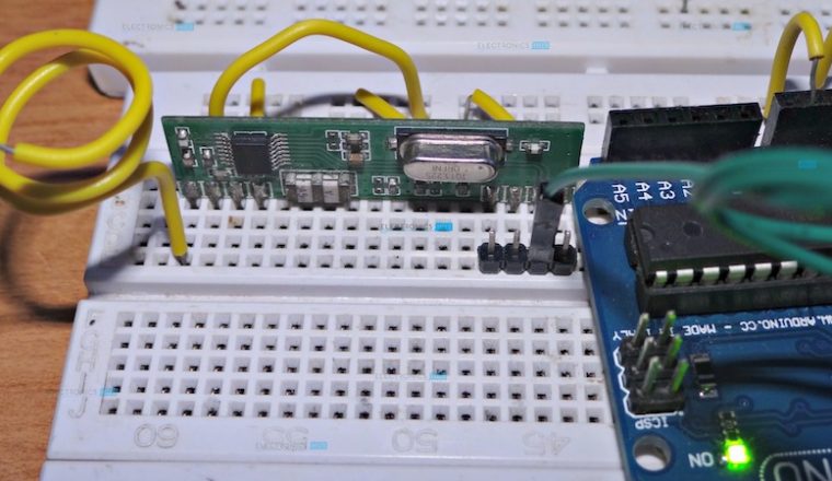
The transmitter part consists of Arduino UNO and the 434 MHz Transmitter module. An external LED can be used but on board LED would be sufficient. The design of the Transmitter part is as follows.
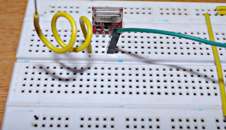
The RF Transmitter Module consists of 4 – pins: VCC, GND, Data and Antenna. VCC and GND pins are connected to 5V and ground respectively. The data pin is connected to any of the digital input / output pin of Arduino. Here, it is connected to Pin 12.
The antenna pin must be connected to an antenna which is nothing but a wire wound in the form of a coil.
We are using the on board LED for demonstration but an external LED along with current limiting resistor can be used.
Receiver Part
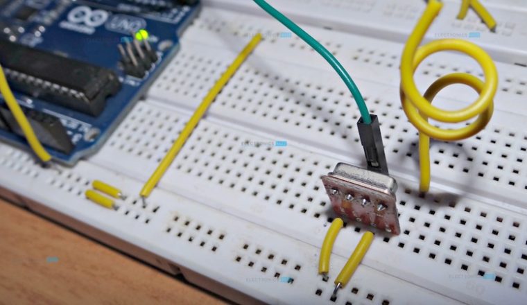
The receiver part consists of Arduino UNO and the 434 MHz Receiver module. An external LED can be used along with a current limiting resistor but on board LED would be sufficient. The design of the Receiver part is as follows.
The RF Receiver Module consists of 4 – pins: VCC, GND, Data and Antenna. VCC and GND pins are connected to 3.3V pin of the Arduino and ground respectively. The data pin is connected to Pin 12 of the Arduino.
An antenna similar to the transmitter module is connected to the antenna pin of the 434 MHz Receiver module. The on board LED which is connected to the 13th pin of Arduino is used in the project although an external LED can always be used.
Working Process
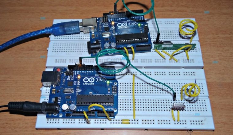
In this project, a simple demonstration of RF Communication with the help of Arduino UNO boards is given. The aim of the project is to successfully transmit data between the RF Transmitter – Receiver modules using two Arduino UNO microcontroller boards. The working of the project is explained here.
Note: The project can be implemented with or without the help of a special library called “VirtualWire.h”. The project implemented here uses the library. If we want to implement the project without the library, then we need to change the receiver part of the circuit.
VirtualWire.h is a special library for Arduino created by Mike McCauley. It is a communication library that allows two Arduino’s to communicate with each other using RF Module i.e. transmitter – receiver pair. This library consists of several functions that are used for configuring the modules, transmission of data by the transmitter module and data reception by the receiver module.
In this project, the transmitter simply sends two characters i.e. it sends the character “1” and with a delay of few seconds, it sends the character “0”. Whenever the “1” is sent, the LED on the transmitting side of the project will be turned ON. As this “1” is transmitted via RF communication, the receiver will receive the data “1”.
When the receiver receives “1”, the Arduino on the receiver side of the project will turn ON the LED on its side.
Similarly, when the data “0” is transmitted by the RF transmitter, the LED on the transmitter side is turned OFF. As a result, the receiver now receives “0” and the LED on the receiver side is also turned OFF.
Hence, the receiver is imitating the actions of the transmitter.
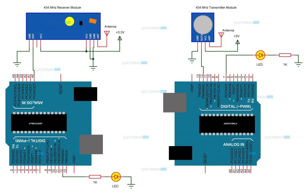
Note: As said earlier, the project uses a special library called VirtualWire. This library used the “Timer” feature of the microcontroller and may affect the timer related properties like PWM for instance.
Hence, the following schematic can be used for a similar implementation without use of any library.
Image Alternative Schematic
The sketch for both the projects i.e. one using the library and the other not using the library are provided.
Applications
- As mentioned in the project introduction, wireless communication using RF Modules has a wide range of applications like
- RC Cars
- Home Automation
- Robotics

26 Responses
i tried to simulate on proteus it didnt work.showed error
do we need to use arduino for the both???
Yes, ofcourse we need two Arduino board for both receiver& transmitter.
The connections which are showed in First RF transmitter module diagram is different from second one .why is that?
can we use only one Arduino .
Any Arduino board would do fine. UNO, Nano, Mega.
Should the antennas on both transmitter and receiver be connected with wires wound?
Not necessary. A simple wire with length of an inch or two would do fine.
Maybe you could help. How i could insert temperature measuring in transmiter circuit – if temperature is less than 22 degrees it sends signal to receiver
Thank you for providing the clear instructions. I’ve done XBee with Arduino, but have not tried this approach. Looks like fun!
can i remove arduino uno board at transmitter side and use it for transmitting data
what is the maximum range of data transmit??
like this can we send audio signals from transmitter to receiver (like MANET(mobile ad-hoc network)).
In this case two mobiles connected to individual arduino boards using bluetooth connection so that communicate to each other if provide transmitter/receiver at each side.This is possible when there is no wifi signal and cell signals.
I interested to do this but I don’t know what type of ad-hoc audio transmitter/receiver module
please can tell the module name
Hello ,
On what basis have you selected threshold ?
what if i connected a reciever pin to one of the digital pins and read the data in 0 or 1 inspite of all this upper and lower threshold. Does it work or not…?
How do I interface a keypad to the transmitter circuit so I can transmit signals by pressing buttons on the keypad.
How can I get the code for both receiver n transmitter with library n without library?
Can we limit the range of the transmitter to a specific value?
If yes, then how can we do it?
i want to use these modules for rc car with 4 push buttons.
can you please tell me how to code for it.
2push button will run 4 left and right motor forward.
other two will run them in backward direction.
why did my simulation using proteus only work on rx board and not on tx board
How secure is the connections? Can anyone send data to the reciever module. Or only the given transmitter can send the data?
good information 🙂
I am beginner.
How can I upload source coding to arduino without connect PC to arduino??
You need a PC with Arduino IDE to compile and upload the code to Arduino. Although, there is an Android App which can work as the PC version (compile and upload). Search for it in the Google Play Store.
Thanks sir, it,s work
sir how to display the received value in Serial monitor and set that value to a new variable.
sir can i import Text file frome one arduino to another arduino using RF Transmitter and Reciver pleas guid me.