You are not alone in encountering the frustrating situation where you accidentally deleted a chat on Instagram and wish you could get it back. However,
Do you want to browse discreetly? Whether it’s for a surprise gift or sensitive research, Safari’s Private Browsing mode, similar to “Incognito,” lets you keep
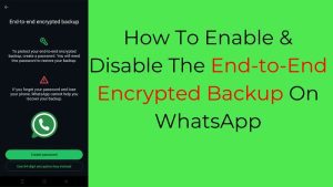
WhatsApp chats are already protected with end-to-end encryption, but what about your chat backups? To ensure your message/chat history remains completely private, WhatsApp offers the
FaceTime is a cornerstone of the Apple ecosystem, renowned for its reliable, high-quality video calls. We all rely on it for those essential connections, so
Snapchat Streaks (Snapstreaks or Streaks) are a fun and engaging feature that tracks how many consecutive days two friends exchange snaps on Snapchat. They have
Creality Falcon A1 Laser Engraver Review An effortless laser engraver, thanks to its built-in camera for alignment and auto material recognition. Even beginners can get