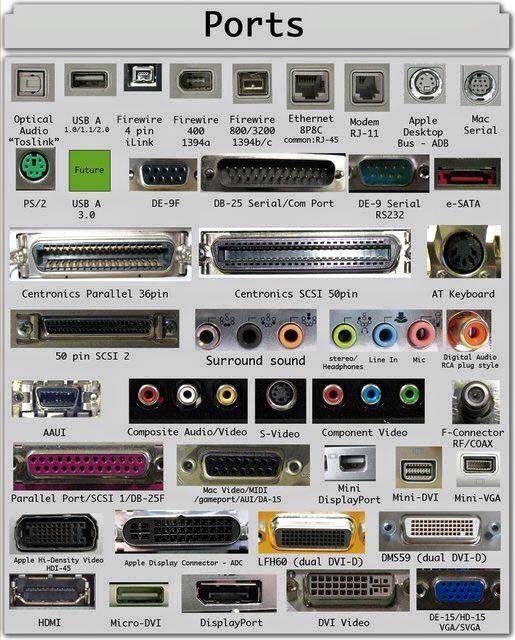
A Computer Port is an interface or a point of connection between the computer and its peripheral devices. Some of the common peripherals are mouse, keyboard, monitor or display unit, printer, speaker, flash drive etc. The main function of the computer ports is to act as a point of attachment, where the cable from the peripheral can be plugged in and allows data to flow from and to the device.
What Are Computer Ports?
A computer port is a physical or virtual interface through which a computer connects to external devices or networks. A computer port is also called as a Communication Port as it is responsible for communication between the computer and its peripheral device. Think of them as the sockets where you plug in different cables.
Classification Of Computer Ports
In Computers, communication ports can be divided into two types based on the type or protocol used for communication. They are Serial Ports and Parallel Ports.
A serial port is an interface through which peripherals can be connected using a serial protocol which involves the transmission of data one bit at a time over a single communication line. The most common type of serial port is a D-Subminiature or a D-sub connector that carry RS-232 signals.
A parallel port, on the other hand, is an interface through which the communication between a computer and its peripheral device is in a parallel manner i.e. data is transferred in or out in parallel using more than one communication line or wire. Printer port is an example of parallel port.
The article gives a brief introduction to different types of ports along with their applications.
Different Types Of Computer Ports And Their Functions
Here is the introduction to different types of ports along with their functions and applications.
HDMI Cables
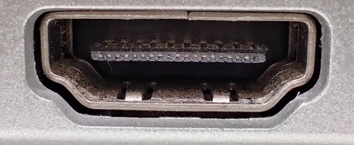
HDMI is an abbreviation of High Definition Media Interface. HDMI is a digital interface to connect High Definition and Ultra High Definition devices like Computer monitors, HDTVs, Blu-Ray players, gaming consoles, High Definition Cameras etc.
HDMI can be used to carry uncompressed video and compressed or uncompressed audio signals. The HDMI port of type A is shown below.
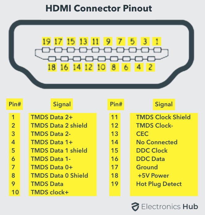
The HDMI connector consists of 19 pins and the latest version of HDMI i.e. HDMI 2.0 can carry digital video signal up to a resolution of 4096×2160 and 32 audio channels. The pinout diagram of an HDMI port is as follows.
Update: The latest version of HDMI is 2.1 with much improved bandwidth, resolution and support from video card manufacturers. While HDMI 2.0 has a data bandwidth of 18 Gbps, the HDMI 2.1 has a staggering 48 Gbps of bandwidth. Coming to the display resolution, HDMI 2.1 supports 4K and 8K at 120 Hz refresh rate. Most modern (at least high end) graphics cards like Nvidia RTX 3090 provide at least a couple of HDMI 2.1 Ports to connect with monitors and TVs.
Mini HDMI
With HDMI 1.3 Version, a new HDMI Port and Connector combination is released called the Mini HDMI. Physically, it is smaller than a regular HDMI Port but has same 19 Pin. Intended for portable devices like laptops, cameras, camcorders, the Mini HDMI Port isn’t that popular.
Micro HDMI
HDMI developers introduced a new HDMI Connector and Port called Micro HDMI with HDMI Version 1.4. Micro HDMI also has 19 pins (just like regular HDMI and Mini HDMI) but the pinout is different.
Micro HDMI is often used in cameras, single board computers (like Raspberry Pi 4), etc. where physically it is difficult to include a regular HDMI port.
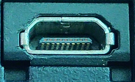
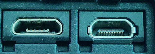
The size of Micro HDMI is significantly smaller than regular HDMI and has some resemblance to a micro–USB Port (sometimes people confuse among the two). The PC port on the left is a micro USB port and the one on the right is a micro HDMI Port.
USB
Universal Serial Bus (USB) replaced serial ports, parallel ports, PS/2 connectors, game ports and power chargers for portable devices.
USB port can be used to transfer data, act as an interface for peripherals and even act as power supply for devices connected to it. There are three kinds of USB PC ports: Type A, Type B or mini USB and Micro USB.
USB Type A
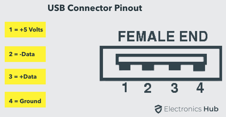
USB Type-A port is a 4 pin connector. There are different versions of Type – A USB ports: USB 1.1, USB 2.0 and USB 3.0. USB 3.0 is the common standard and supports a data rate of 400MBps.
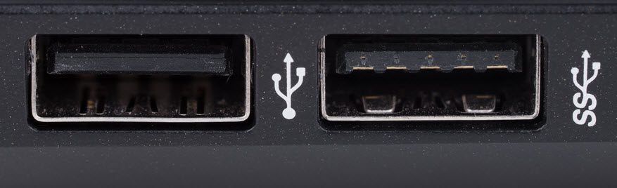
USB 3.1 is also released and supports a data rate up to 10Gbps. Usually, but not all the times, the USB 2.0 is Black color coded and USB 3.0 is Blue. The following image shows USB 2.0 and USB 3.0 ports.
The pinout diagram of USB Type – A computer port is shown below. The pinout is common to all standards of Type – A.
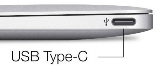
USB Type C
USB Type – C is the latest specification of the USB and is a reversible connector. USB Type – C is supposed to replace Types A and B and is considered future proof.
The port of USB Type – C consists of 24 pins. The pinout diagram of USB Type – C is shown below. The latest USB Specifications (USB4) is an USB-C only specification i.e., only USB type C devices can be used with USB4 specifications.
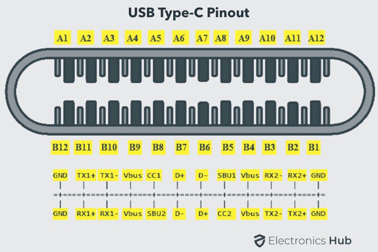
In the latest USB4 specification, USB Type C Devices can support speeds up to 40 Gbps.
USB Power Delivery specifications allow USB devices to supply power to devices connected to the USB Port. USB Type – C can handle a current of 5A at 20V (only Power Delivery certified USB Type-C Ports).
This feature of handling high current is used in the latest Fast Charging Technology where a Smart Phone’s battery will reach its full charge is very less time. So, USB Type C Ports can provide up to 100W of power (which can be used for charging mobile phones and laptops).
In fact, the latest Apple M1 Mac Books use 61W USB C Power Adapter.
Ethernet RJ45 Cable
Ethernet is a networking technology that is used to connect your computer to Internet and communicate with other computers or networking devices.
The interface that is used for computer networking and telecommunications is known as Registered Jack (RJ) and RJ – 45 port in particular is used for Ethernet over cable. RJ-45 connector is an 8 pin – 8 contact (8P – 8C) type modular connector.
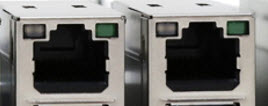
The latest Ethernet technology is called Gigabit Ethernet and supports a data transfer rate of over 10Gigabits per second. The Ethernet or a LAN port with 8P – 8C type connector along with the male RJ-45 cable is shown below.
The un-keyed 8P – 8C modular connector is generally referred to the Ethernet RJ-45. Often, RJ-45 ports are equipped with two LEDs for indicating transmission and packet detection.
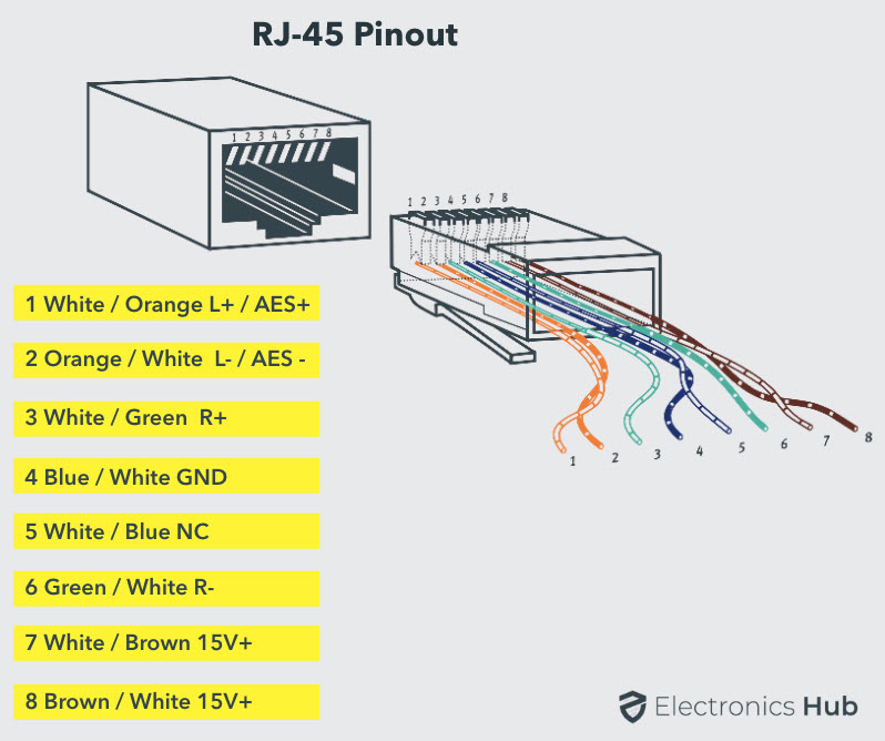
As mentioned earlier, an Ethernet RJ-45 port has 8 pins and the following picture depicts the pinout of one.
RJ-11
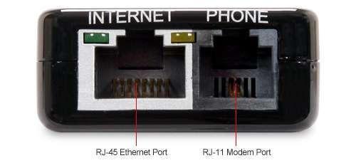
RJ-11 is another type of Registered Jack that is used as an interface for telephone, modem or ADSL connections. Even though computers are almost never equipped with an RJ-11 port, they are the main interface in all telecommunication networks.
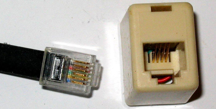
RJ-45 and RJ11 ports look alike but RJ-11 is a smaller port and uses a 6 point – 4 contact (6P – 4C) connector even though a 6 point – 2 contact (6P – 2C) is sufficient. The following is a picture of an RJ-11 port and its compatible connector.
The following image can be used to compare RJ-45 and RJ-11 ports.
Audio Ports
Audio ports are used to connect speakers or other audio output devices with the computer. The audio signals can be either analogue or digital and depending on that the port and its corresponding connector differ.
Surround Sound Connectors or 3.5 mm TRS Connector
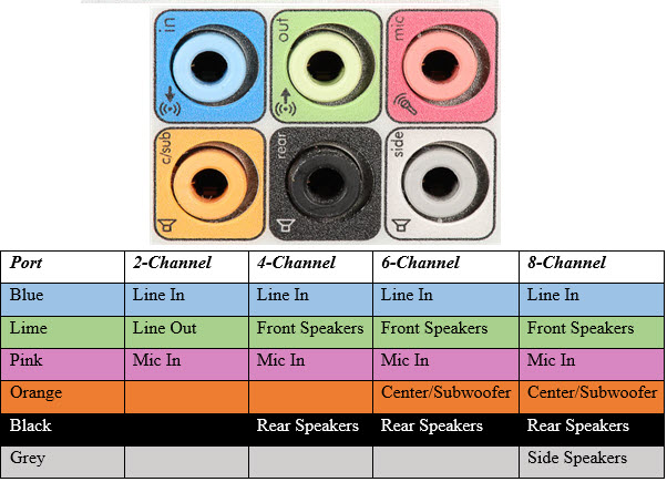
It is the most commonly found audio port that can be used to connect stereo headphones or surround sound channels. A 6 connector system is included on majority of computers for audio out as well as a microphone connection.
The 6 connectors are color coded as Blue, Lime, Pink, Orange, Black and Grey. These 6 connectors can be used for a surround sound configuration of up to 8 channels.
Video Ports
VGA Port
VGA port is found in many computers, projectors, video cards and High Definition TVs. It is a D-sub connector consisting of 15 pins in 3 rows. The connector is called as DE-15.
VGA port is the main interface between computers and older CRT monitors. Even the modern LCD and LED monitors support VGA ports but the picture quality is reduced. VGA carries analogue video signals up to a resolution of 648X480.
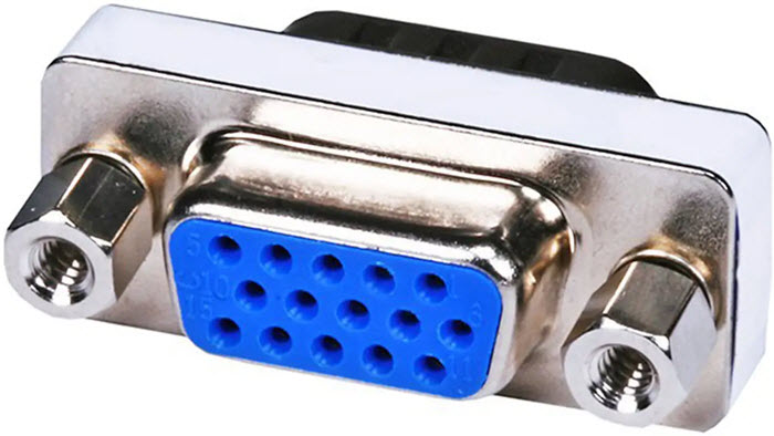
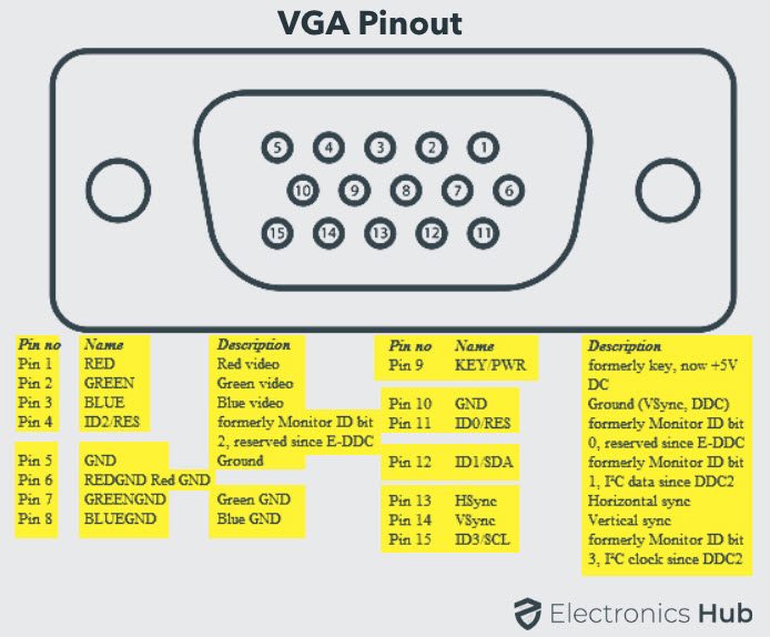
With the increase in use of digital video, VGA ports are gradually being replaced by HDMI and Display Ports. Some laptops are equipped with on-board VGA ports in order to connect to external monitors or projectors. The pinout of a VGA port is shown below.
Digital Video Interface (DVI)
DVI is a high speed digital interface between a display controller like a computer and a display device like a monitor. It was developed with an aim of transmitting lossless digital video signals and replace the analogue VGA technology.
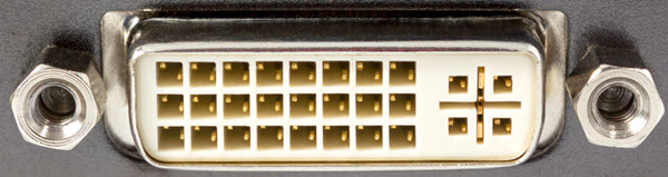
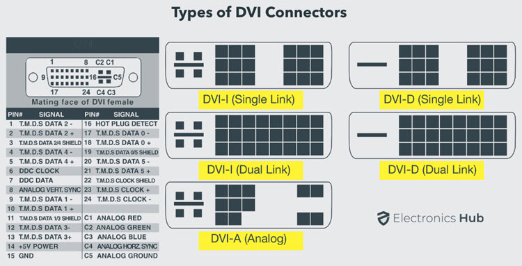
There are three types of DVI connectors based on the signals it can carry: DVI-I, DVI-D and DVI-A. DVI-I is a DVI port with integrated analogue and digital signals. DVI-D supports only digital signals and DVI-A supports only analogue signals.
The digital signals can be either single link or dual link where a single link supports a digital signal up to 1920X1080 resolution and a dual link supports a digital signal up to 2560X1600 resolution. The following image compares the structures of DVI-I, DVI-D and DVI-A types along with the pinouts.
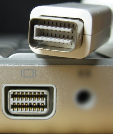
Mini-DVI
Mini-DVI port is developed by Apple as an alternative to Mini-VGA port and is physically similar to one. It is smaller than a regular DVI port.
It is a 32 pin port and is capable of transmitting DVI, composite, S-Video and VGA signals with respective adapters. The following image shows a Mini-DVI port and its compatible cable.
Micro-DVI
Micro-DVI port, as the name suggests is physically smaller than Mini-DVI and is capable of transmitting only digital signals.
This port can be connected to external devices with DVI and VGA interfaces and respective adapters are required. In the following image, a Micro-DVI port can be seen adjacent to headphone and USB ports.

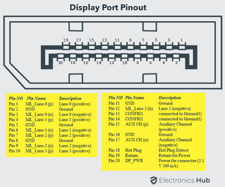
Display Port
Display Port is a digital display interface with optional multiple channel audio and other forms of data. Display Port is developed with an aim of replacing VGA and DVI ports as the main interface between a computer and monitor.
The latest version DisplayPort 1.3 can handle a resolution up to 7680 X 4320.

The Display Port has a 20 pin connector, which is a very less number when compared to DVI port and offers better resolution. The pin out diagram of a Display Port is shown below.
Update: DisplayPort 1.4a is the latest (in production) version of DisplayPort Specification with support for 4K (3840 x 2160) at 120 Hz or 8K (7680 x 4320) at 60 Hz. An improved DisplayPort version 2.0 specification is released in June of 2019 with an increased bandwidth of 77.37 Gbps (approximately).
Mini DisplayPort
Apple introduced a miniature version of DisplayPort and called it Mini DisplayPort (mDP or Mini DP). Even though Mini DisplayPort has 20 pins, the physical size of the connector is smaller than a regular DisplayPort and the pin out is also different.
Most laptops provide Mini DisplayPort as an additional video out option in addition to HDMI.
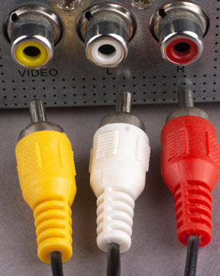
RCA Connector
RCA Connector can carry composite video and stereo audio signals over three cables. Composite video transmits analogue video signals and the connector is as yellow colored RCA connector.
The video signals are transmitted over a single channel along with the line and frame synchronization pulses at a maximum resolution of 576i (standard resolution).
The red and white connectors are used for stereo audio signals (red for right channel and white for left channel).
Component Video
Component Video is an interface where the video signals are split into more than two channels and the quality of the video signal is better that Composite video.
Like composite video, component video transmits only video signals and two separate connectors must be used for stereo audio. Component video port can transmit both analogue and digital video signals.
The ports of the commonly found Component video uses 3 connectors and are color coded as Green, Blue and Red.

S-Video
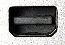
S-Video or Separate Video connector is used for transmitting only video signals. The picture quality is better than that of Composite video but has a lesser resolution than Component video.
The S-Video port is generally black in color and is present on all TVs and most computers. S-Video port looks like a PS/2 port but consists of only 4 pins.

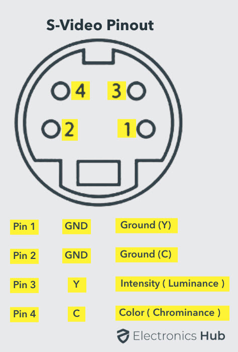
Out of the 4 pins, one pin is used to carry the intensity signals (black and white) and other pin is used to carry color signals. Both these pins have their respective ground pins. The pinout diagram of an S-Video port is shown below.
PS/2 Port
PS/2 connector is developed by IBM for connecting mouse and keyboard. It was introduced with IBM’s Personal Systems/2 series of computers and hence the name PS/2 connector. PS/2 connectors are color coded as purple for keyboard and green for mouse.

PS/2 is a 6-pin DIN connector. The pin out diagram of a PS/2 female connector is shown below.
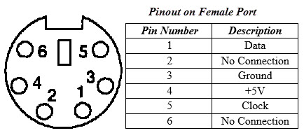
Even though the pinout of both mouse and keyboard PS/2 ports are same, computers do not recognize the devise when connected to wrong port.
PS/2 port is now considered a legacy port as USB port has superseded it and very few of the modern motherboards include it as a legacy port.
Serial Port
Even though the communication in PS/2 and USB is serial, technically, the term Serial Port is used to refer the interface that is compliant to RS-232 standard. There are two types of serial ports that are commonly found on a computer: DB-25 and DE-9.
DB-25
DB-25 is a variant of D-sub connector and is the original port for RS-232 serial communication. They were developed as the main port for serial connections using RS-232 protocol but most of the applications did not require all the pins.
Hence, DE-9 was developed for RS-232 based serial communication while DB-25 was rarely used as a serial port and often used as a parallel printer port as a replacement of the Centronics Parallel 36 pin connector.
DE-9 or RS-232 or COM Port
DE-9 is the main port for RS-232 serial communication. It is a D-sub connector with E shell and is often miscalled as DB-9. A DE-9 port is also called as a COM port and allows full duplex serial communication between the computer and it’s peripheral.
Some of the applications of DE-9 port are serial interface with mouse, keyboard, modem, uninterruptible power supplies (UPS) and other external RS-232 compatible devices.
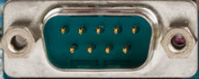
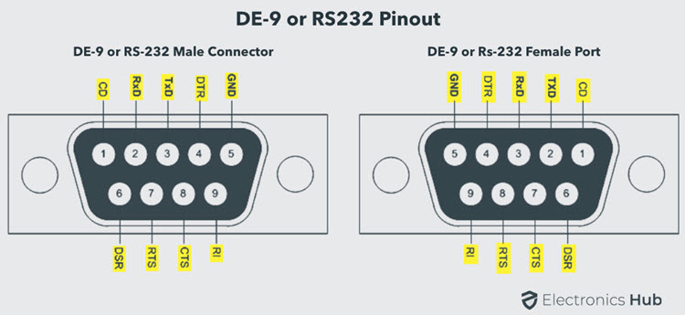
The pinout diagram of DE-9 port is shown below.
The use of DB-25 and DE-9 ports for communication is in decline and are replaced by USBs or other ports.
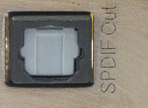
S/PDIF / TOSLINK Cable
The Sony/Phillips Digital Interface Format (S/PDIF) is an audio interconnect used in home media. It supports digital audio and can be transmitted using a coaxial RCA Audio cable or an optical fiber TOSLINK connector.
Most computers home entertainment systems are equipped with S/PDIF over TOSLINK. TOSLINK (Toshiba Link) is most frequently used digital audio port that can support 7.1 channel surround sound with just one cable. In the following image, the port on the right is an S/PDIF port.
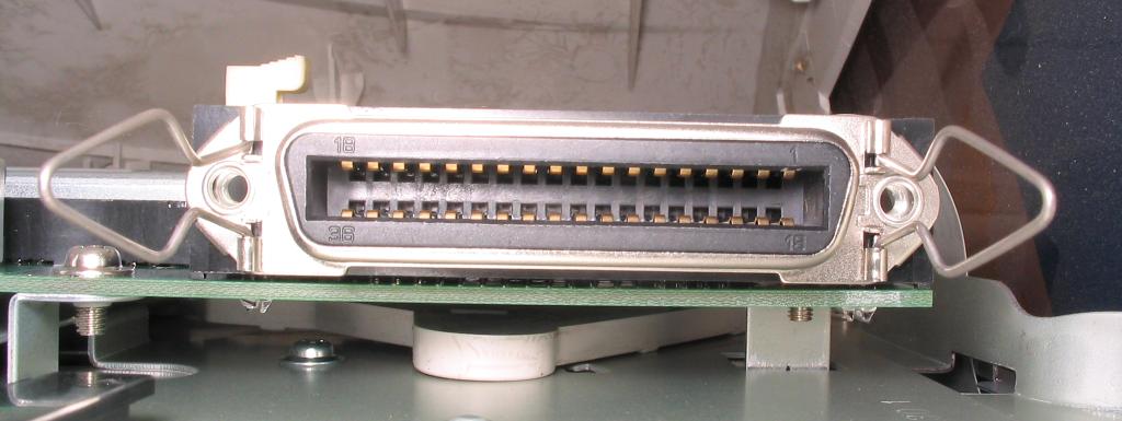
Parallel Port or Centronics 36 Pin Port
Parallel port is an interface between computer and peripheral devices like printers with parallel communication. The Centronics port is a 36 pin port that was developed as an interface for printers and scanners and hence a parallel port is also called as a Centronics port.
Before the wide use of USB ports, parallel ports are very common in printers. The Centronics port was later replaced by DB-25 port with parallel interface.
e-SATA Connectors
e-SATA is an external Serial AT Attachment connector that is used as an interface for connecting external mass storage devices. Modern e-SATA connector are called e-SATAp and stands for Power e-SATA ports.
They are hybrid ports capable of supporting both e-SATA and USB. Neither the SATA organization nor the USB organization has officially approved the e-SATAp port and must be used at user’s risk.
Thunderbolt Ports
Thunderbolt is an interface developed by Intel in collaboration with Apple that combines PCI Express (PCIe) and DisplayPort into a single connection. It allows high-speed data transfer and the connection of multiple devices through a single port.
Thunderbolt ports are used primarily for connecting external devices like monitors, storage drives, and docking stations to computers. They support various peripherals simultaneously, enabling fast data transfer and video output.
Thunderbolt 3:
With a data transfer rate of up to 40 Gbps, Thunderbolt 3 ports can transmit video signals and data simultaneously. They use USB-C connectors and are found on many modern laptops, including MacBooks and high-end PCs.
Thunderbolt 4:
This newer version of Thunderbolt supports the same 40 Gbps data transfer rate but introduces stricter hardware requirements for devices to improve compatibility and reliability. It also supports longer cables and can connect to up to two 4K displays or one 8K display.
Thunderbolt ports are versatile and are increasingly adopted in professional environments for their high performance and ability to daisy-chain multiple devices, reducing cable clutter and enhancing productivity.

95 Responses
thanks
thanks de que!!!
Thanks
I have learned something I’m appreciating
Thanks for the info. really appreciate
thanx for the knoweledge
Thanks very helpful
I’m just in level 12 and I’m 17 years old and these info would help me study for my computer exams ???
Nice info. thanks electronics hub….
thanks for r your concern…I like the explanations
Thanks a lot 4 the information
Useful Info.
Thanks
Hi, very informative. There is one port not mentioned. It’s called Thunderbolt port. I’m asking because I received an Apple Thunderbolt Display and would like to use it in my PC. Only my PC doesn’t have a thunderbolt port. Is there a way to hook both together by using adapters. Thanks.
It is very informative thanks sir.
Thanks for helping
i,thank a lot.i have much that i did not expect,all who don’t know about electronic you are welcomed….
i have learn something new today
Thanks so much….
Merci?
Amazing I got my homework done….I appreciate
Thanks got my homework done
Nice Information
Thanks for helping me with my assignment
It’s very helpful for me. A lot of information .
Thanks sir
Thank you. Very informative and helpful for CompTIA preparation. Thanks
thanks much for the knowledge
Wow…… Highly appreciated the nice work….i used to struggle to understand those ports….. Thank u
Its very useful for students, thank you so much for this information.
Collected material. …very useful ….all in one
like accessories ?
This was very helpfull for me to understand the peripheral connection…
Thankyou very much..
Thank you very good and good quality for text
What’s the difference in USB types?
I’ve got a USB that can be plugged in either way round (it’s not the rounded Type-C), and what could be a USB 2.0 that is white!
Thanks a lot
very good
Just discovered some new ports that I always see but pay little attention to. Thanks for sharing this knowledge.
thank you very much from the middle east
Thanks
Thanks for the info deeply informative and i get-the -hang of all i was looking for pertaining to connectors and interfaces,thanks am now a pro .
Thanks for the info, is nice
Sahi ha
Great information! The photos really help. Very nicely done.
damn tysm
thank you. You helped me to pass my exam
Yes that’s correct by the way. thanks for the help though ☺️?
What are the important ports
Thank you!
thanks ….
thank you so much, now i wont fail my test
The time and effort you spent to prepare and share such a great information is GREATLY APPRECIATED!
Thank you so much!
very helpful
wow…. ! very comprehensive indeed ! keep on writing more for educating the net e-zins !
very nice info
It is very useful. Thank you.
Thank you.. I have learnt a lot..really appreciate
thanks
lovely information about ports
nice info, I learnt a lot Thank you
Thanks very much for this vital information
Thank you so much for this , it helped greatly
Thank You very much
that pinout help me 🙂
Thanks!!! It has helped me in my assignments.
am very appreciating that information, be blessed sir.
Very useful and precise. Thank you so much team.
very nice info
Very helpful
Thanks, This has been very useful.
Thanks. It’s really something knowledgeable.
Nice one, really good one.
Yes that’s correct by the way. thanks for the help though ☺️?
thanks u sir for this vital information
Wonderful work done, thanks a lot for the information
thanks lot the good guides of the computer parts and functions
thanks lot, the good guides of the computer parts and functions including is it
Thanks for your help God bless you
We really appreciate this article, it is very very helpful, we will be very grateful if such kind of written article will continued to be given to us
Thanks, it’s really something knowledgeable
Good information, very helpful
Hello guys… Can you please assist with this…. Name five interface or connections of the back panel of the computer and specify the use of each.
its fine and understandable thanks a lot
very nice your website
Very helpfull
you really saved me to waste 1 month of searching, thank you very much.
Very educative. Thanks.
Thanks for the information. This helps explain connections in equipment when mixing Antique things to new things.
Information was very helpful, thank you so much
Wow ! Wow Wow!!! Amazing work done.. Well arranged and pictures are clear to see… Keep it up
Very useful information. Thank you.
It’s more usefully, Thanks ????
thanks sir, your information help me.
Thanks ????????
Thanks a lot! it’s really helpful.
that was amaizing
Thank you so much for the effort you put in to post this, I am a visual person and the photos really help.
I really enjoyed working with you. It was an excellent experience. Thank you
THANK YOU…????????????
Thanks????very helpful
Thanks very much for the more knowledge u provide