In this tutorial, we will learn about the pinout information of ESP32. I will use the 30-pin ESP32 Development Board to demonstrate the ESP32 Pinout. You will also learn about some important peripherals of the ESP32 Microcontroller and its associated pins, what GPIO pins can be used in your project, etc.
Why Do We Need To Learn ESP32 Pinouts?
ESP32-based boards come in a variety of shapes and sizes and pinout of each board is different to other. Also, not all pins of the ESP32 Microcontroller SoC will be available on a development board as some pins might be permanently tied to a dedicated function.
One such case is the Flash Memory. We know that all ESP32 boards come with 4 MB of Flash Memory to store the programs. So, some of the GPIO Pins (6 pins to be specific) are connected to SPI Flash IC and you cannot use those pins as regular GPIO Pins.
Hence, it is important to understand the pinout of popular ESP32 boards so that you will know what pins are available for use in projects.
Introduction To ESP32 Pin Layout
The ESP32 Microcontroller IC is available in a 48-pin QFN (Quad Flat No Leads) package. Since it is a QFN package, it is difficult solder the IC on to the PCB, if you are interested in making an ESP32 Board by yourself.
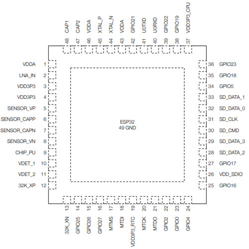
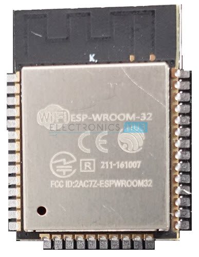
So, what Espressif Systems (the developers of ESP32) did is, they took the ESP32 IC and made a small module board with edge castellations. One popular version of such module board is called ESP-WROOM-32.
In addition to the ESP32 IC, the ESP-WROOM-32 also contain a 4 MB SPI Flash IC, a 40 MHz Crystal Oscillator, PCB Antenna and some discrete passive components to make a working system.
You can use this board in your hardware design (as it takes care of the complex RF section of the PCB) and make a development board or a breakout board or even a commercial product.
This is what third-party module manufacturers do. They take the ESP-WROOM-32 Module, design a break-out board based on this module with user friendly pins, USB Port, RESET and BOOT switches etc.
ESP-WROOM-32 Pinout
Let us start exploring the ESP32 Pinout by taking a look at the ESP WROOM 32 Pinout. The following image show the pinout of a typical ESP-WROOM-32 Module. It consists of 38-pin (14 pins on each long edge and 10 on bottom short edge).
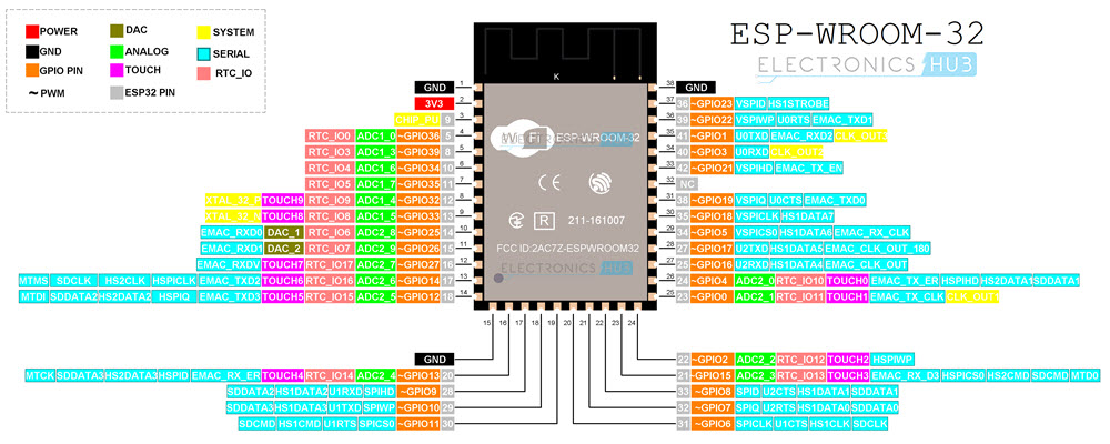
The other short edge is left for PCB Antenna. If you notice the previous ESP-WROOM-32 image, the Microcontroller and other components are not visible as they placed under the RF Shield.
Use this pinout of ESP-WROOM-32 module as a reference if you are using such module in your hardware design.
ESP32 Pinout
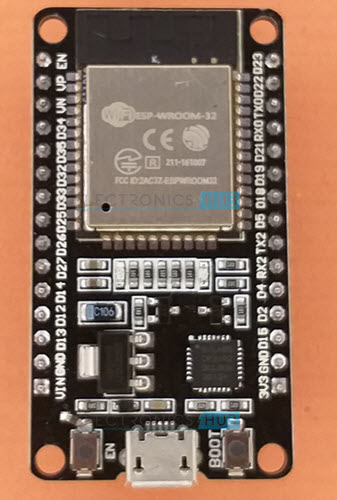
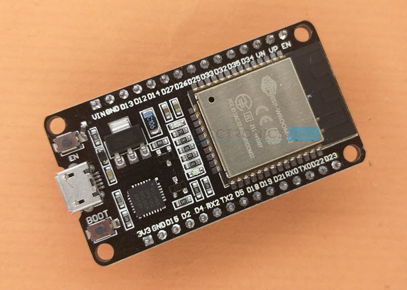
One of the most popular ESP32 Development Boards available today is the 30-pin version shown in the above image. It consists of ESP-WROOM-32 as the baseboard and additionally a few pins and components to easily interact with ESP32.
The following image shows the pinout of a 30-pin ESP32 DevKit Development Board.
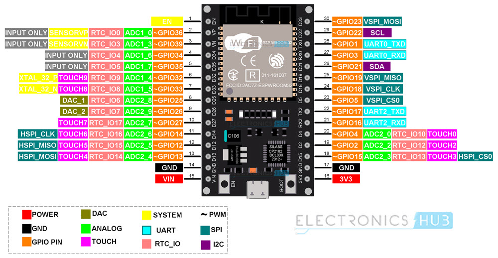
As you can see from the image, each pin has more than one possible functionality. While using a pin for particular task, you have to double check its alternative functions.
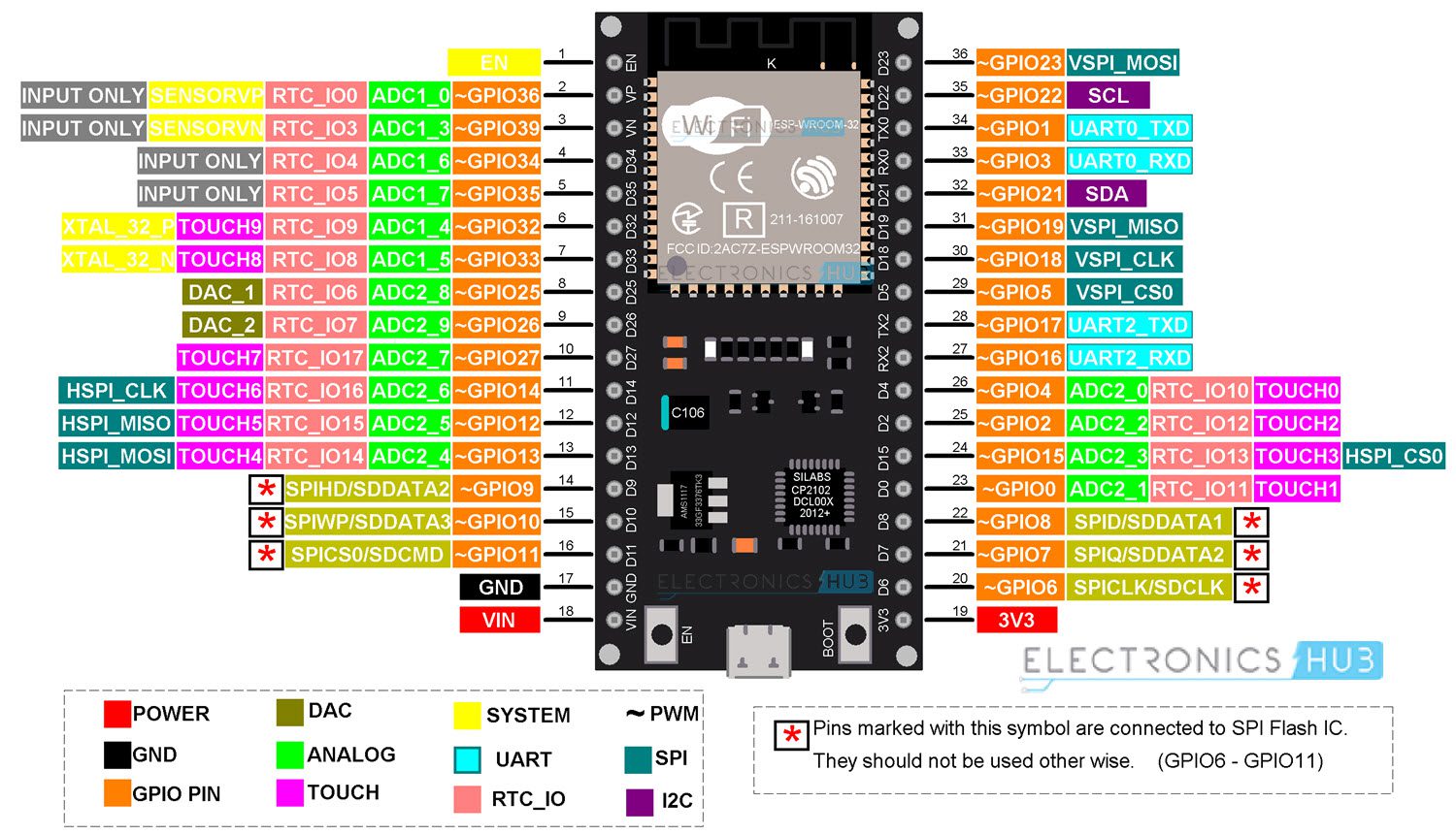
Another version of ESP32 DevKit Board comes with 36-pins. This version is not as popular as the 30-pin version. But if you happen to have a 36-pin ESP32 board, the following pinout will be very helpful.
Note that the pinout of both the 30-pin and the 36-pin versions of ESP32 Development Boards are very identical except for some pins at the bottom. In the 36-Pin version, 6 GPIO pins (GPIO6 through GPIO11) are used for SPI Flash IC. So, they shouldn’t be used for other purposes. Finally, you just get one extra pin (GPIO0 – Pin 23).
Important ESP32 Peripherals
Now that we have seen a little bit about ESP32 Pinout, let us focus on some of the important peripherals of ESP32 and their associated pins. The ESP32 Microcontroller has the following peripherals:
- 34 Programmable GPIOs
- 18 12-bit ADC Channels
- 2 8-bit DAC Channels
- 16 PWM Channels
- 3 UART Interfaces
- 3 SPI Interfaces
- 2 I2C Interfaces
- 2 I2S Interfaces
- 10 Capacitive Touch Sensing GPIOs
- 16 RTC GPIOs
ESP32 GPIO Pinout
The most commonly used peripheral is the GPIO. ESP32 has 34 GPIO pins with each pin carrying out more than one function (only one will be active). You can configure a pin as either a GPIO or an ADC or an UART in the program.
ADC and DAC pins are predefined and you have to use the manufacturer specified pins. But for the other functions like PWM, SPI, UART, I2C etc. you can assign them to any appropriate GPIO pin through software.
RTC GPIO
ESP32 has 16 RTC GPIOs, which are part of the RTC Low-Power subsystem. These pins can be used to wake ESP32 from deep sleep as external wake-up source.
ADC
ESP32 has two 12-bit SAR Analog to Digital Converter Modules with 8-channels and 10-channels each. So, ADC1 and ADC2 blocks combined together have 18 channels of 12-bit ADC.
With 12-bit resolution, the output Digital values will be in the range of 0 – 4093.
DAC
ESP32 Microcontroller has two independent 8-bit Digital to Analog Converter channels to convert digital values to analog voltage signals. The DAC has internal resistor network and uses power supply as input reference voltage.
The following two GPIO Pins are associated with DAC functionalities.
- DAC1 — GPIO25
- DAC2 — GPIO26
Capacitive Touch GPIOs
The ESP32 SoC has 10 capacitive-sensing GPIOs, which can detect variations in capacitance on a pin due to touching or approaching the GPIO Pin with a finger or stylus. These Touch GPIOs can be used in implementing capacitive touch pads, without any additional hardware.
SPI
The ESP32 Wi-Fi chip features three SPI blocks (SPI, HSPI and VSPI) in both master and slave modes. SPI is used to interface with Flash Memory. So, you have two SPI interfaces.
I2C
There are two I2C interfaces in ESP32 with complete flexibility on assigning pins i.e., SCL and SDA pins for both I2C interfaces can be assigned in the program by the user.
If you are using Arduino IDE, then the default I2C pins are:
- SDA – GPIO21
- SCL – GPIO22
PWM
The PWM Controller in ESP32 have 16 independent PWM waveform channels with configurable frequency and duty cycle. The PWM waveform can be used to drive motors and LEDs. You can configure the PWM signal frequency, channel, GPIO pin and also the duty cycle.
What ESP32 GPIO Pins To Use?
Let us now take a look at a table which specifies the GPIO pins and their input / output capabilities.
|
GPIO Pin |
Pin on ESP32 | Information |
| 0 | – |
Pulled HIGH. Connected to BOOT Button |
|
1 |
TX0 | Do not use while TXing |
| 2 | YES |
Pulled LOW |
|
3 |
RX0 | Do not use while RXing |
| 4 | D4 |
Pulled LOW |
|
5 |
D5 | Pulled HIGH |
| 6 | – |
Connected to SPI Flash IC |
|
7 |
– | Connected to SPI Flash IC |
| 8 | – |
Connected to SPI Flash IC |
|
9 |
– | Connected to SPI Flash IC |
| 10 | – |
Connected to SPI Flash IC |
|
11 |
– | Connected to SPI Flash IC |
| 12 | D12 |
Pulled LOW. Boot fails if pulled HIGH as it sets voltage of internal voltage regulator. |
|
13 |
D13 | |
| 14 | D14 |
|
|
15 |
D15 | Pulled HIGH |
| 16 | RX2 |
UART2 RX |
|
17 |
TX2 | UART2 TX |
| 18 |
D18 |
|
|
19 |
D19 | |
| 21 | D21 |
I2C SDA |
|
22 |
D22 | I2C SCL |
| 23 | D23 |
|
|
25 |
D25 | |
| 26 |
D26 |
|
|
27 |
D27 | |
| 32 |
D32 |
|
|
33 |
D33 | |
| 34 | D34 |
Digital Input Only. No Digital Output. |
|
35 |
D35 | Digital Input Only. No Digital Output. |
| 36 | YES |
Digital Input Only. No Digital Output. |
|
39 |
YES |
Digital Input Only. No Digital Output. |
GPIOs Connected to SPI Flash IC
If you take a look at the schematic of ESP-WROOM-32 Module, then you will see that GPIO6 to GPIO11 are connected to SPI Flash Memory IC. Even if these GPIO pins are accessible (which are not in 30-pin ESP32 Board), do not use them for any other purpose.
Input only GPIO
There are 4 GPIO pins which are capable of acting as Digital input-only pins. They are GPIO34, GPIO35, GPIO36 and GPIO39.
Interrupts
All GPIO pins are capable of interrupts.
Boot Strapping Pins
ESP32 SoC has 5 boot strapping pins. They are:
- GPIO0 (HIGH during BOOT)
- GPIO2 (LOW during BOOT)
- GPIO5 (HIGH during BOOT)
- GPIO12 (LOW during BOOT)
- GPIO15 (HIGH during BOOT)
These pins are used to put the microcontroller into flashing mode or bootloader mode.
FAQs
ESP-WROOM-32 is a module containing the ESP32 microcontroller, flash memory, and other supporting components. ESP32 DevKit boards use this module and add features like USB ports, voltage regulators, and accessible pin headers for easier development.
GPIO6 to GPIO11 are connected internally to the SPI flash memory used by the ESP32 for program storage. Using these pins for general input/output can interfere with the chip’s operation and may cause boot failures.
GPIO34, GPIO35, GPIO36, and GPIO39 are input-only pins. They cannot be used for digital output or PWM, but are useful for sensor readings or ADC input.
Certain GPIOs are bootstrapping pins and have predefined logic states during boot:
- GPIO0 – Must be HIGH
- GPIO2 – Must be LOW
- GPIO5 – Must be HIGH
- GPIO12 – Must be LOW
- GPIO15 – Must be HIGH
Incorrect states on these pins can prevent the ESP32 from booting properly.
Yes, ESP32 allows flexible pin mapping for most peripherals like PWM, SPI, UART, and I2C through software. However, some functions (like ADC, DAC, and touch sensing) are fixed to specific GPIOs defined by the hardware.
Conclusion
This is a complete guide on ESP32 Pinout. You learned about the pinout of the ESP-WROOM-32 Module, ESP32 DevKit Development Board and some important peripherals of the ESP32,. You also learned what GPIOs to use and what GPIO Pins not to use in your design. Additionally, being familiar with how peripherals like ADC, DAC, PWM, I2C, UART, and SPI are mapped allows for flexible and optimized use of the board’s capabilities. Before starting any project, always refer to the board-specific pinout to ensure correct pin selection and avoid common boot or functionality issues.
If you still have any questions, feel free to share them with us in the comments section below.

One Response
Excellent paper on using this device. Thank-you.