In this tutorial, I will show you How to Program STM32F103C8T6 using Keil uVision and STM32CubeMX Code Generator Software. You will learn how to install the Software (both Keil and STM32CubeMX), configure the software as per our requirements and upload the code using ST-Link Debugger and Programmer.
Introduction
Till now, I have implemented several STM3F103C8T6 MCU based projects using the STM32 Blue Pill Board. In all these projects, I have used the Arduino IDE as the tool for writing the code as well as uploading the code to STM32 using an USB to UART Converter.
Using Arduino IDE for STM32 projects is very easy as the familiar Arduino terminology can be applied to STM32F103C8T6 as well. This is acceptable for beginners but if you want to seriously learn the working of the powerful STM32 MCU, then this is not the right way.
The proper way is to step away from the Arduino world and enter a more professional set of tools in terms of both the software as well as the hardware. Speaking of software, I suggest you to use the ARM’s Keil uVision IDE. This is a great tool for working with ARM based MCUs like our STM32F103C8T6 and it also supports proper debugging.
Coming to the hardware, we have to use a separate hardware for programming (as well as debugging) the STM32 Blue Pill Board. This hardware is called as ST-LINK/V2. It is as in-circuit programmer and debugger developed by STMicroelectronics. Although the original programmer will be expensive, there are many third-party programmers that are compatible with the original programmer and cost very less.
There is another important software called the STM32CubeMX. This is also provided by STMicroelectronics and is used to generate the code for a specific STM32 MCU as well as a particular IDE.
I will show you how to use all these software and hardware so that you can easily program STM32F103C8T6 using Keil uVision and STM32CubeMX.
Download and Install STM32CubeMX
First, let us start with the STM32CubeMX Code Generator Tool. Download this software from this official STMicroelectronics website. You have to login to ST in order to download the software. At the time of writing this tutorial, the version of STM32CubeMX is 5.6.1. Install the software and open it.

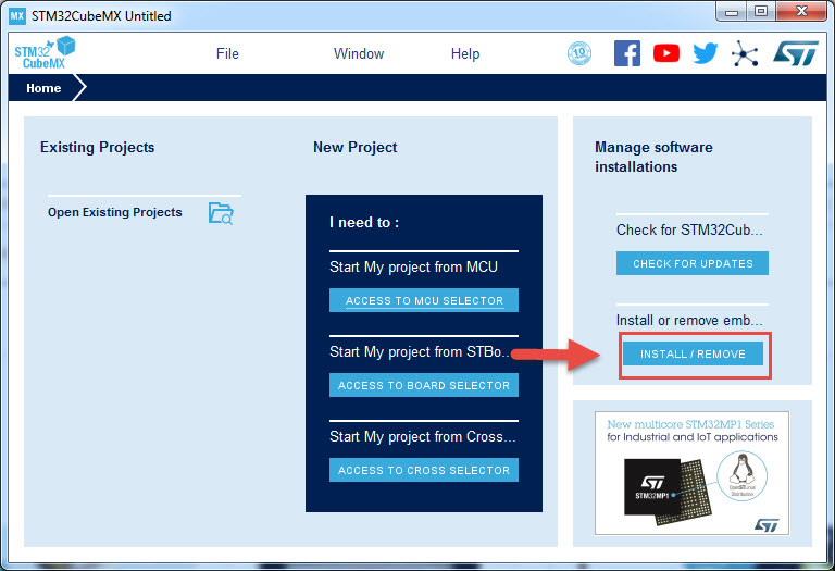
On the right side in the application, click on the install or remove embedded software packages option. A new window will open.
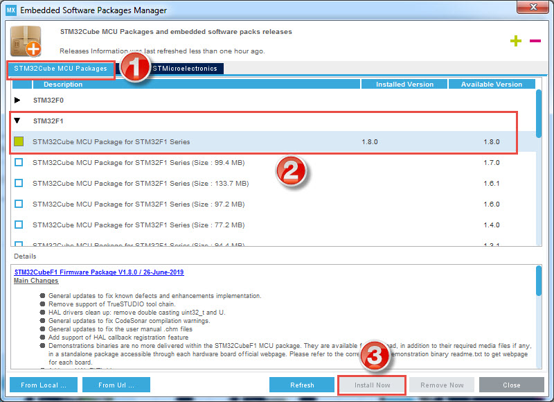
In that, select the STM32Cube MCU Packages option and expand the STM32F1 tab (since our MCU is STM32F103C8T6). The latest package at the time is 1.8.0. Select the latest version and click on Install Now option at the bottom. It will download and install the MCU Package. After completion, you can close this window.
New STM32CubeMX Project
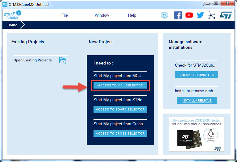
Now, in the main window, select the ACCESS TO MCU SELECTOR option. A new window will open for us to select the MCU that we are working on.
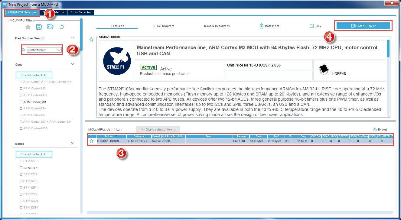
In the new window, under the MCU/MPU Selector tab, search for “STM32F103C8”. On the right side, our MCU will be listed. Select that MCU and on the top right corner click on the Start Project option.
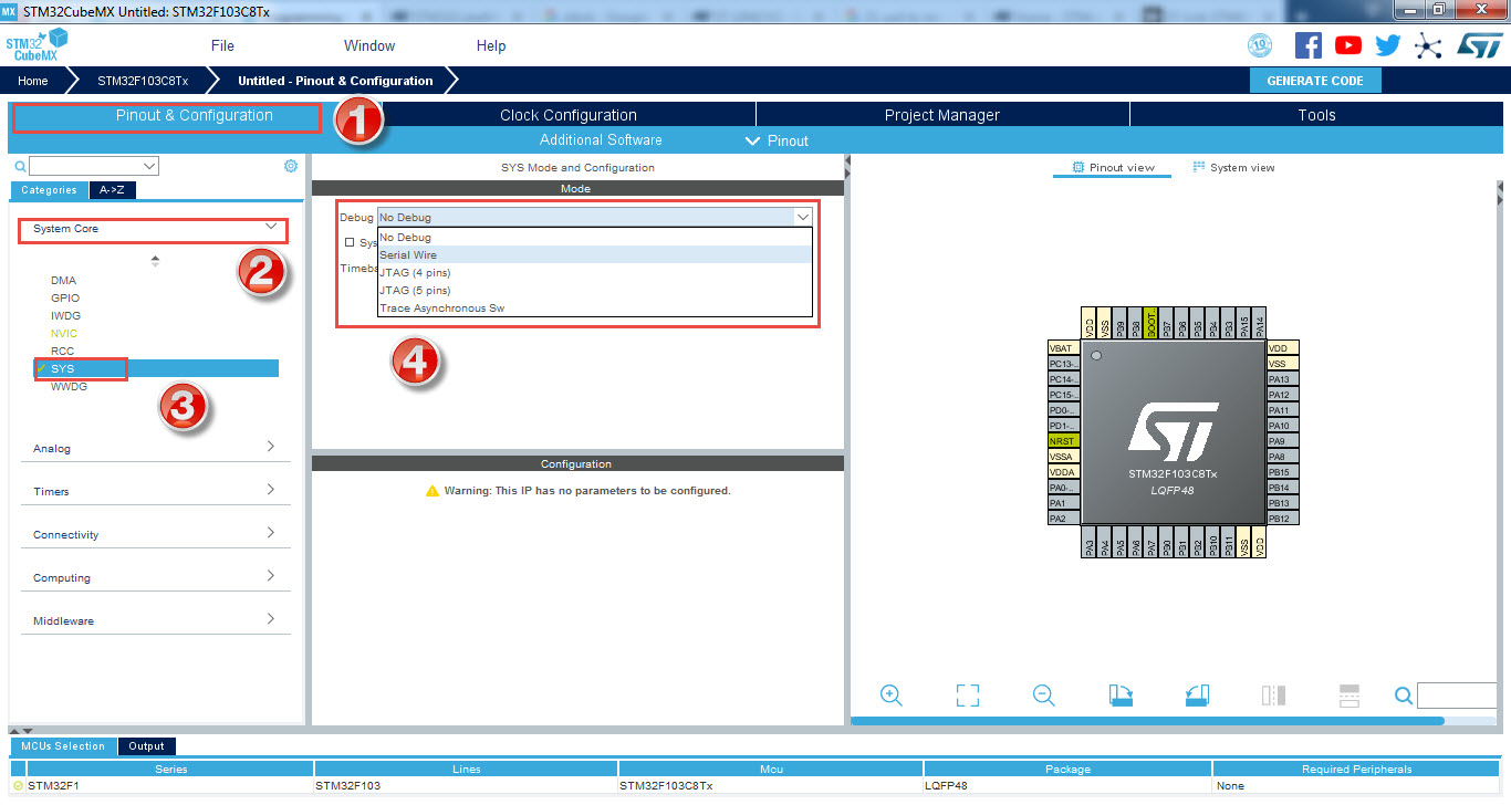
The main project window will open with a pinout of STM32F103C8T6 MCU on the right and configuration options on the left. In the Pinout and Configuration Tab, expand the System Core block and select the SYS option. Select the Debug as Serial Wire. As soon as you select this option, you can observe that the Pins PA13 and PA14 are SWDIO and CK i.e. Serial Wire Debug Data and Clock pins.
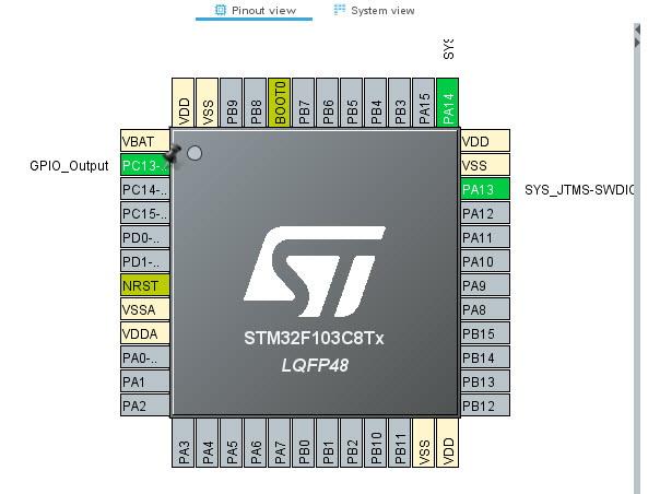
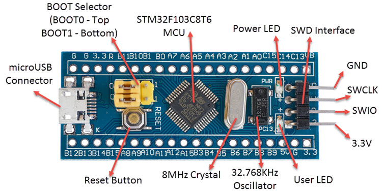
The next step is to configure the LED present on the Blue Pill Board. We know from the schematic of the STM32 Blue Pill that a Green LED is connected to PC13. Hence, zoom into the Pinout view of the STM32F103C8T6 MCU and on the PC13 Pin, make a left click and select GPIO_Output option. We can change the label of this pin by right clicking on the PC13 Pin and selecting Enter User Label option. I have used the label “LED_Green”.
This completes the basic setup for the project. Other thing that we can configure is the Clock but the STM32 MCU uses the internal RC Oscillator by default (configured in the SystemInit Function). So, we can leave the Clock Configuration as it is.
In the next step, select the Project Manager Tab and select an appropriate location and name for your project. In my case, I have named the project as “STM32_LED_Blinky”. Also, select the Toolchain / IDE as MDK-ARM, which is nothing but the Keil uVision IDE.
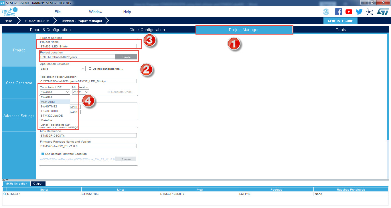
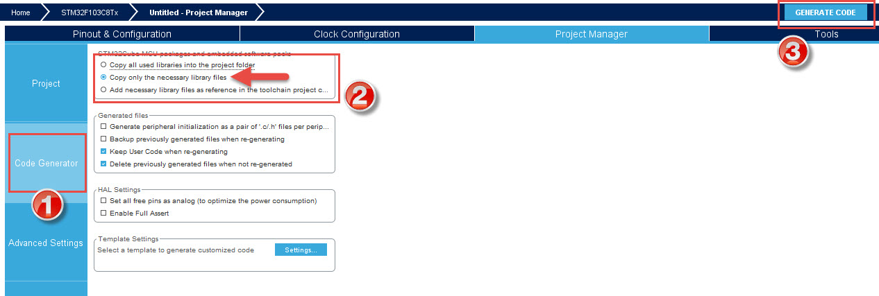
After selecting the toolchain, click on the Code Generator option and select the copy only the necessary library files option. After this, you can click on GENERATE CODE option. The tool will create a project based on the IDE selected and also copies the necessary library files for the project. After the code is generated, you can close the STM32CubeMX Software.
A Brief Note on ST-LINK Debugger and Programmer
Before proceeding further, let us take a brief look at the ST-LINK Programmer and Debugger. Its latest revision is known as ST-LINK/V2. The cheaper version of the ST-LINK/V2 Programmer is shown in the image below.

One end of the programmer is a USB Male Connector, which you can plug-in to a computer. The other end of the programmer consists of the JTAG / Serial Wire Debugging (SWD) Interface. The pinout of this interface is neatly printed on top of the debugger Module.
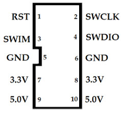
From these pins, we have to use the 3.3V, GND, SWDIO and SWCLK pins. If you remember the pinout of the STM32F103C8T6 Blue Pill Board, the SWD interface is neatly placed on the right side.
Download and Install Keil uVision
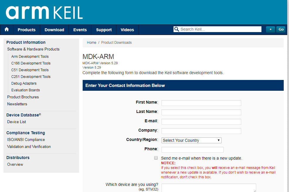
Now, let us proceed with the installation of the Keil uVision MDK for ARM. Using this link, enter your contact information and download the evaluation version of the MDK-ARM. At the time, MDK-ARM Version 5.29 was the latest.
After installing, the MDK, you don’t need to open the Keil uVision as we will be doing that from the previously generated code using STM32CubeMX.
New Keil uVision Project
Instead of creating a new Keil uVision Project, we can use the project created during the STM32CubeMX Code Generation. Open the folder where the STM32CubeMX Project was saved earlier and open the MDK-ARM Folder.
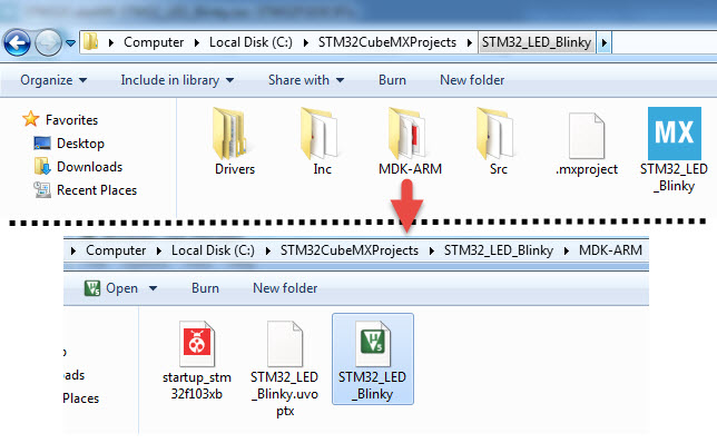
In this folder, there is a Keil MDK Project file STM32_LED_Blinky. Double click on this file and the Keil uVision will open with all the source code and library files. After this, you can open the main.c file.
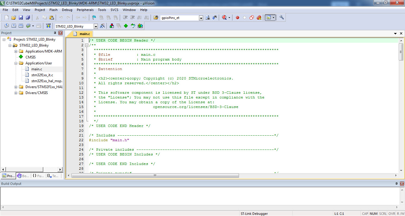
Modifying the Code for Blinking LED
The code generated using STM32CubeMX is just the initialization code and doesn’t do anything other than initializing some peripherals as per the user configuration. In order to do implement an application, like Blinking an LED for example, you have to add the necessary code.
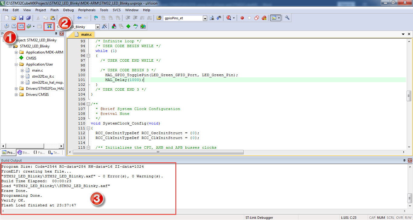
In the main.c file, scroll down to the main function and in the while (1) loop, add the following code.
HAL_GPIO_TogglePin(LED_Green_GPIO_Port, LED_Green_Pin);
HAL_Delay(1000);
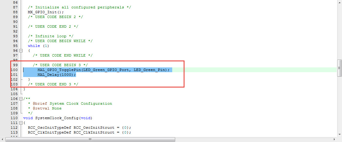
This code will Blink the LED with 1 second delay. Now, you can “Build” the project using either F7 or the shortcut in the IDE. Keil uVision will now compile the code and display the result of the compilation at the bottom. If there are any errors or warnings, the line number will be displayed at which the error or warning is present so that you can easily correct the mistakes.
Components Required
Before understanding how to Program STM32F103C8T6 using Keil uVision, let us take a look at the components and the connections.
- STM32F103C8T6 MCU based STM32 Blue Pill Board
- ST-LINK/V2 Debugger and Programmer
- Connecting Wires
Connect ST-LINK with STM32F103C8T6
Connect the SWDIO pin of ST-LINK/V2 to the SWIO pin of the STM32 Blue Pill. Also connect the SWCLK pin of ST-LINK/V2 to the corresponding SWCLK pin of the STM32 Blue Pill. Finally, connect the 3.3V and GND pins.
ST-LINK/V2 GND 3.3V SWDIO SWIO SWCLK
STM32 Blue Pill
GND
3.3V
SWCLK
How to Program STM32F103C8T6 using Keil uVision?
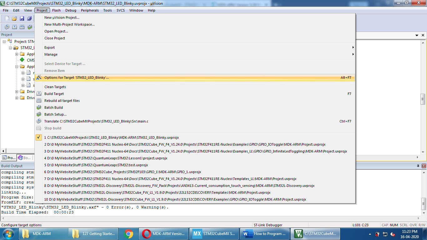
After making the above connections, we can proceed to Program STM32F103C8T6 using Keil uVision. Connect the ST-LINK/V2 Debugger to the computer. In the Keil uVision, click on Project Tab and select Options for Target…… link.
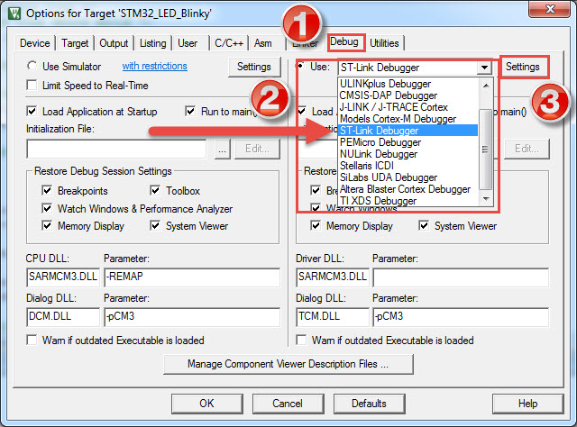
Select the Debug tab and select ST-Link Debugger. After that, click on Settings option adjacent to it.
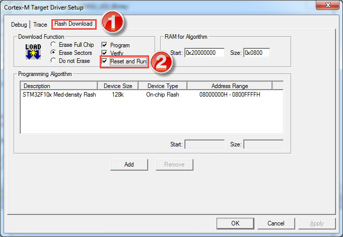
Go to Flash Download option and check the Reset and Run option. After that, click on OK to save the settings and click on OK once again to close the Options for Target.
Now, if you made any changes to the code, save all the changes and select Rebuild option, which is next to the build option. If there are no errors, click on Download option. Keil uVision, with the help of ST-LINK/V2, will now program your STM32F103C8T6. You can see the status at the bottom.
Conclusion
In this tutorial, I have shown you how to Program STM32F103C8T6 using Keil uVision, ST-LINK/V2 Debugger and Programmer.

One Response
I have an STM32F429IET6, could you please help me to burn either Arduino or Mbed code into the STM32F429IET6?