Traditional Doorbells are wired devices and are usually fixed at one place. They are becoming obsolete because of these reasons and are gradually being replace by advanced Wireless Doorbell Devices. With a wireless doorbell, the position of the switch and the bell is not fixed.
We can place it anywhere we want and also the installation is pretty simple. The setup of wireless doorbell doesn’t require any internal wiring. Also, if the wired doorbell is not fixed while construction, we need to make holes for wiring and installation.
Arduino based Wireless Doorbell
In this project, we have designed an Arduino based Wireless Doorbell using simple hardware. The project is implemented using RF Module for wireless communication and also an Arduino UNO board to analyze the data.
Arduino based Wireless Doorbell Circuit Diagram
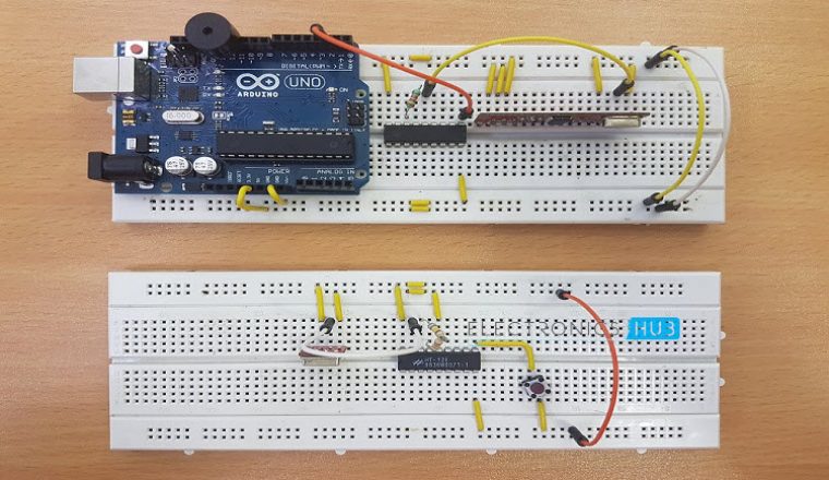
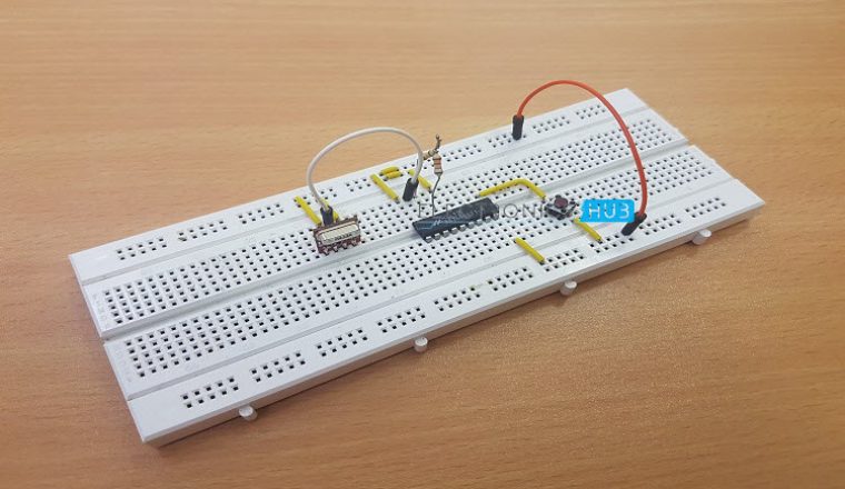
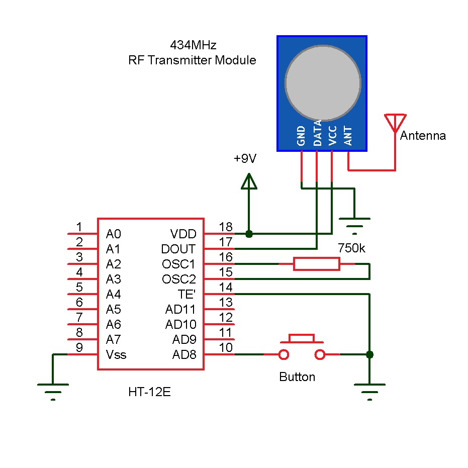
Wireless Doorbell Transmitter Circuit Diagram
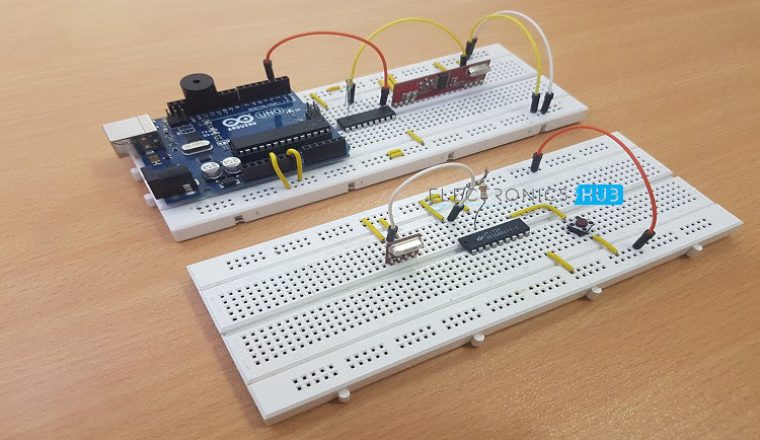
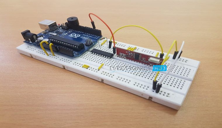
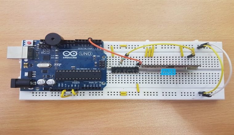
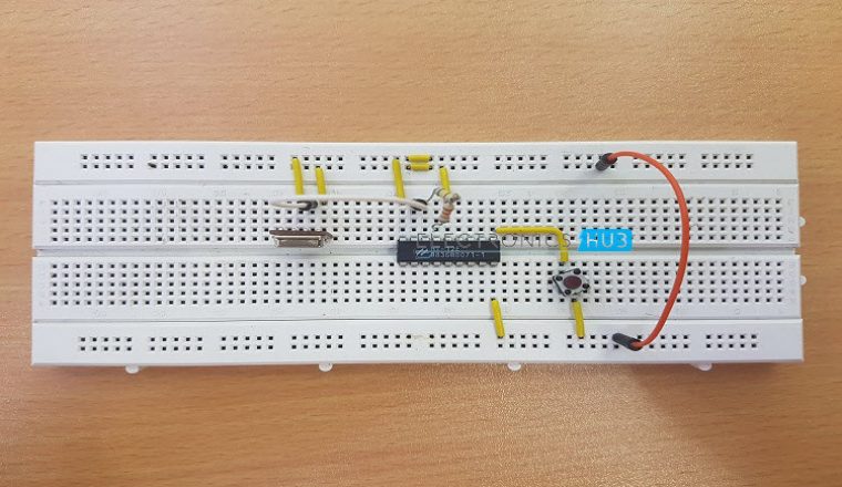
 Wireless Doorbell Receiver Circuit Diagram
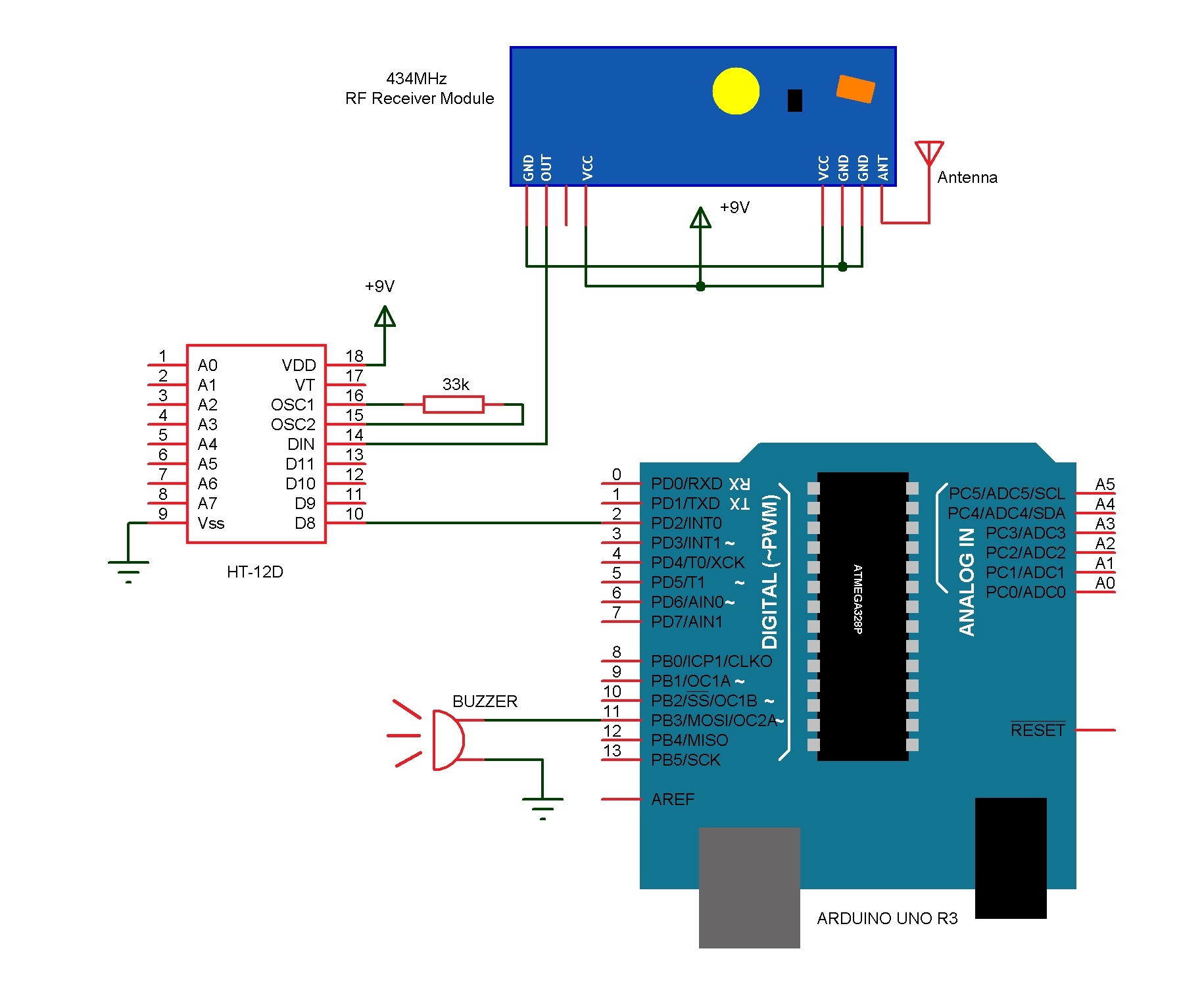
 Components
For Transmitter
- 434 MHz RF Transmitter Module
- HT – 12E Encoder IC
- 750 KΩ Resistor
- Push Button
- Power Supply
- Connecting Wires
- Prototyping Board (Breadboard)
For Receiver
- Arduino UNO
- 434 MHz RF Receiver Module
- HT – 12D Decoder IC
- 33 KΩ Resistor
- Small Buzzer
- Power Supply
- Connecting Wires
- Prototyping Board (Breadboard)
Component Description
RF Transmitter – Receiver Module:The wireless communication in this project is implemented using RF Transmitter – Receiver pair. A 434 MHz RF Transmitter – Receiver Module is used in this project. Up to 500 feet or 150 meters of distance can be possible with this module.
Arduino UNO:The main task of Arduino UNO is to determine the logic state of the decoded output from the Decoder IC. It also activates the buzzer once the desired logic state is detected.
HT – 12E Encoder IC: HT – 12E Encoder IC is often used with the RF Transmitter Module. The Encoder IC converts the parallel data from its input to serial data for the RF Transmitter module to transmit.
HT – 12D Decoder IC: HT – 12D Decoder IC is the counter part of the Encoder IC. It is often used with RF Receiver Module. The RF Receiver receives the serial data from the RF Transmitter. The Decoder IC takes this serial data and converts it back to the parallel data.
Circuit Design
Design of Transmitter Circuit
The transmitter consists of a 434 MHz RF Transmitter Module, HT – 12E Encoder IC, 750 KΩ Resistor and a push button. The design of the transmitter circuit is very simple. Pins 18 and 9 are connected to supply and ground terminals respectively.
The data out pin (Pin 17) of HT – 12E is connected to data pin of the RF Transmitter Module. A 750 KΩ is connected between the oscillator pins (Pins 15 and 16) of the HT – 12E. The transmission enable pin (Pin 14) is connected to ground. A push button is connected between AD8 (Pin 10) and ground. Other connections are shown in the circuit diagram.
Design of Receiver Circuit
- The receiver part of the project consists of 434 MHz RF Receiver Module, HT – 12D Decoder IC, 33 KΩ Resistor, Arduino UNO and a small buzzer.
- Pins 18 and 9 i.e. VDD and Vss pins are connected to supply and ground terminals respectively. The data in pin (Pin 14) of the decoder IC is connected to the data pin of the RF Receiver Module. A 33 KΩ Resistor is connected between the oscillator pins (Pins 15 and 16) of the decoder IC.
- The D8 pin (Pin 10) is connected to Pin 2 (or any digital I/O pin) of Arduino UNO. A small buzzer is connected between pin 11 of Arduino and ground.
Working of the Project
The aim of this project is to design a simple wireless doorbell. The working of the project is explained here. For explaining the working of the project, all the connections are made as per the circuit diagram.
NOTE: Make sure that the Transmitter Part of the Project is switched on before the Receiver Part. This is to ensure that the RF Transmitter and Receiver Modules are properly paired.
In order to ring the bell (or buzzer in this case), we need to push the button on the transmitter side of the circuit. When the button is pushed on the transmitter side, a logic ‘0’ will be detected by the Encoder IC. The Encoder IC will transmit this data serially through the RF Transmitter Module.
The transmitted data will be received by the RF Receiver Module and is given to the Decoder IC. The Decoder IC, then decodes the serial data to parallel data and transmits the Logic ‘0’ to Arduino.
In the Arduino UNO’s, it is programmed such that, whenever a Logic ‘0’ is detected by the Arduino, the buzzer is turned on. Hence, whenever the button is pressed, the buzzer is turned on wirelessly.
Code
Advantages
- The advantage of using RF Transmitter – Receiver based Wireless Doorbell is that it is very easy to design the circuit and implement.
- The range of the transmission is fairly large. Hence, it is suitable for large homes.
- Another advantage over Bluetooth based data transmission is it doesn’t require any smart phone or Bluetooth enabled phone or any other Bluetooth device.
- In case the system is implemented using a Wi-Fi network, we need to make sure that both the transmitter and receiver are connected to the Wi-Fi network.
- Another wireless technology which can be used for Wireless Doorbell is IR. But the problem is that its range is less and also it is a Line of Sight Communication.
Limitation
- Both the Transmitter and Receiver parts of the circuit must be always turned on i.e. there should always be power.
- No additional security like camera integration and hence, the ringer of the bell can’t be determined.
Applications
- The Wireless Doorbell implemented in this project is just a demonstration of the idea. But the idea can be extended to actual, real time wireless doorbell system.
- Since the mode of communication is RF, the range is considerably large that other wireless technologies.
- The project is suitable for homes, shops, garages, hospitals, offices etc.
Construction and Output Video
Recommended read:

12 Responses
is this project is good
Hello, I have a problem with the code, can you help me?
*the selected serial port avrdude: stk500v2_RecieveMessage() : timeout does not exist or your board is not connected
Please please help me!
Hi, I figured the first error, I uploaded the code, but the buzzer is always on, not working when I push the button. Always making the noise
change the while loop to if? And add a code that let the ring last for a few second or something
How can we construct it using two Arduinos , One at transmittor and one at receiver end?
You can use two XBee shield modules
Using 2 Arduinos would be simple, but I am not sure why unless you are trying to do more.
The switch would be wired as a digital input to the Arduino then configure one of the GPIO as a digital output connected to the HT12E then write code to drive the output low when the button is pressed.
In this case the Arduino is just passing the switch state; are you trying to do something else with the Arduino on the transmitter side?
i’m not an EE student, so bear with me. I’m just doing this just for fun. Does this project works with different tranmitter/receiver module? such as 433 module? if yes, what is the different between them?
what are the library files required for uploading the program in arduino uno board.
please send me a video how to dump the program in arduino board.
Can some please modify the code because the buzzer is always on even if i don’t press the button
Please send me code for above project
Suggest a redesign. CPU not really needed if simply ringing bell.
Slightly more ambition would have Arduino record timestamps about WHEN door activity occurred and maybe capture photos from camera. Then use regular Wireless Ethernet module to both ring bells on standard home controls and also allow queries about when people were at door or photos of who delivered or stole your packages.
Also by using standard wireless Ethernet home controls, it becomes easy to have other actions like ringing bells in occupied rooms in certain order (e.g. day sleeper last). Or take alternative action if no is home.