Metal detector is a very common device that is used for checking persons, luggage or bags in shopping malls, hotels, cinema halls, etc. to ensure that person is not carrying any metals or illegal things like guns, bombs etc. Metal Detectors detect the presence of metals.
There are different types of metal detectors like hand held metal detectors, walk through metal detectors and ground search metal detectors. Metal detectors can be created easily and the circuit for a basic metal detector is not that complex.
Metal Detector Circuit
In this project, we have designed a simple DIY type Metal Detector Circuit using very simple components that can be used in our homes and gardens.
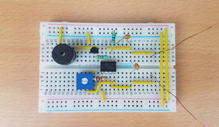
Metal Detector Circuit Diagram
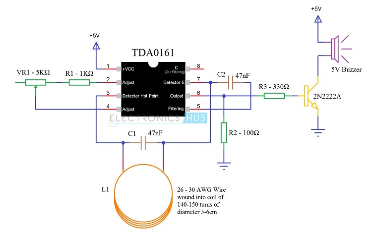
The following image shows the circuit diagram for the metal detector circuit.
Components Required
- 1 x TDA0161 Proximity Detector IC
- 2 x 47nF Capacitors (Ceramic Capacitor code 473)
- 1 x 1 KΩ Resistor (1/4 Watt)
- 1 x 330 Ω Resistor (1/4 Watt)
- 1 x 100 Ω Resistor (1/4 Watt)
- 1 x 5 KΩ Potentiometer
- 1 x 2N2222A (NPN Transistor)
- 1 x 5V Buzzer
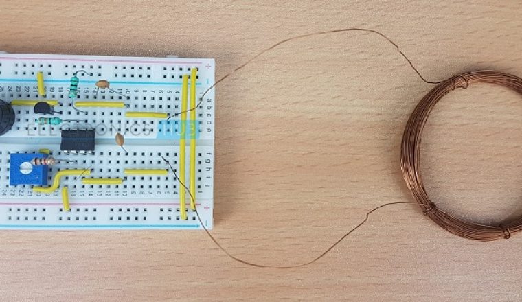
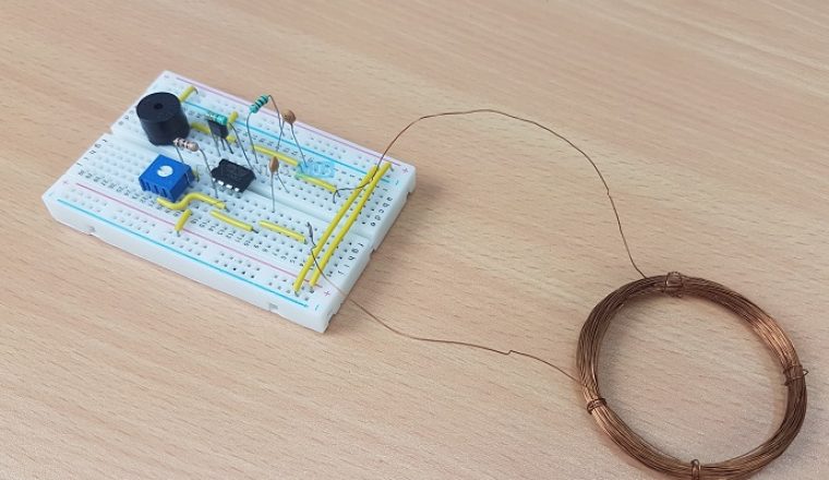
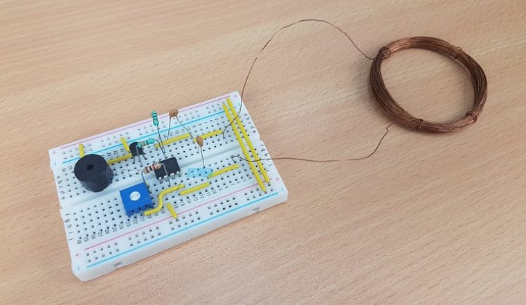
- Coil (copper wire of 26 – 30 AWG is taken and it is wound in to a coil of diamater 5 – 6 cm and 140 – 150 turns)
- Additional Components (for LED)
- 1 x 220 Ω Resistor (1/4 Watt)
- 1 x 5mm LED
Component Description
TDA0161 Proximity Detector IC: TDA0161 is a Proximity Detector IC manufactured by STMicroelectronics. It can be used detect metal objects by detecting the slight changes in the high frequency Eddy current losses.
The TDA0161 IC acts as an oscillator with the help of externally tuned circuit. The changes in supply current will determine the output signal i.e. current is high when a metal object is near and it is low when there is no metal object.
TDA0161 has 8 pins and it comes in Dual in – line Package (DIP). The following image shows the pin diagram of TDA0161 IC.
NOTE: According to STMicroelectronics, TDA0161 Proximity Detector IC is obsolete. If it is available in the market, go ahead and make this fun project. If it isn’t available, try to find a replacement IC. We will try to update if any similar IC is available. If you find any Proximity Detector ICs, please mention it in the comments section.
Coil (Inductor): We have taken a 30 AWG Copper wire for this project. It is then wound in to a coil using a 5.8cm diamater reference. The coil consists of 140 – 150 turns.
Metal Detector Circuit Explanation
- When the LC circuit that is L1 and C1 has got any resonating frequency from any metal which is near to it, electric field will be created which will lead to induces current in the coil and changes in the signal flow through the coil.
- Variable resistor is used to change the proximity sensor value equal to the LC circuit, it is better to check the value when there is coil not near to the metal. When the metal is detected the LC circuit will have changed signal. The changed signal is given to the proximity detector (TDA 0161), which will detect the change in the signal and react accordingly. The output of the proximity sensor will be of 1mA when there is no metal detected and it will be around 10mA when coil is near to the metal
- When the output pin is high the resistor R3 will provide positive voltage to transistor Q1. Q1 will be turned on and led will glow and buzzer will give the buzz. Resistor r2 is used to limit the current flow.
Block Diagram of Metal Detector
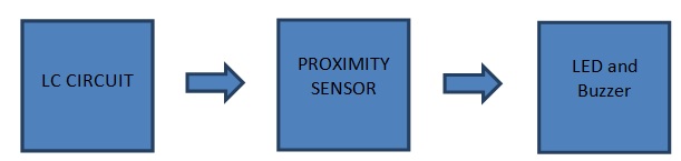
There are three main parts in the metal detector circuit: the LC Circuit, the Proximity Sensor , output LED and the Buzzer. The coil and the capacitor C1, which are connected in parallel, will form the LC circuit.
Proximity sensor(TDA0161), is triggered by this LC cirucit if any metal is detected.The Proximity sensor will then turn on the led and produces alarm using buzzer.
LC Circuit: LC circuit has inductor and capacitor connected in parallel.This circuit sarts resonating when there is same frequency material near to it. The LC circuit charges capacitor and inductor alternatively.When the capacitor is charged fully ,charge is applied to inductor.
Inductor starts charging and when charge across the capacitor is nil, it draws charge from the inducutor in reverse polarity. Then inductor charge is reduced and again the process repeats.Note inductor is a magnetic field storage device and capacitor is electric field storage device.
Proximity Sensor: The proximity sensor can detect the objects with out any physical interference. The proximity sensor will work same as infrared sensor, proximity also release a signal, it will not give output unless and until there is no change in the reflected back signal.
If there is a change in signal it will detect and give the output accordingly. There are different proximity sensors for example to detect plastic material we can use capacitive type proximity and for metals we should use inductive type.
Working
The LC Circuit, which consists of L1 (coil) and C1, is the main metal detector part of the circuit. With the help of this LC Circuit, which is also called as Tank Circuit or Tuned Circuit, the TDA0161 IC acts as an oscillator and oscillates at a particular frequency.
When the LC circuit detects any resonating frequency from any metal which is near to it, electric field will be created which will lead to induces current in the coil and changes in the signal flow through the coil.
Variable resistor is used to change the proximity sensor value equal to the LC circuit, it is better to check the value when the coil is not near any metal object. When the metal is detected, the LC circuit will have changed signal.
The changed signal is given to the proximity detector (TDA 0161), which will detect the change in the signal and react accordingly. The output of the proximity sensor will less than 1mA when there is no metal detected and it will be around 10mA (usually greater than 8mA) when coil is near to the metal.
When the output pin is high, the resistor R3 will provide positive voltage to transistor Q1. Q1 will be turned on and LED will glow (not shown in the circuit) and buzzer will be activated.
Advantages
- The Proximity Detector IC TDA0161 based Metal Detector Circuit is a very simple and easy to construct metal detector that can be used to detect small metals in our homes, offices and gardens.
- There is need for any microcontroller as the Proximity Sensor will be sufficient to implement the project.
Disadvantages
- The main disadvantage of this Metal Detector Circuit is the range of detection. The metal object has to be at a distance of 10mm for the detector to detect it.
Applications
- This simple Metal Detector can be used to identify metals like iron, gold, silver etc.
- Since it is a simple project, we can use this in our home to scan for nails, metal scraps etc. which are not easily spotable by naked eye.
Related Posts:

55 Responses
hi,good time
i’m from iran
i need many circuits gold scan or metal detector power.
tanks
Thanks for the post.
Thank you
good
I am confused at the bobbin inductor part !!
I dunno what it is …and why its in pf !!?
Please help !!!
please send the complete details about the components used in circuit with its design part……if possible please upload a video of circuit working
can u please send a video that how to make this project
Can u send me metal detector circuit componetnts list???
nyc, very help full
Please post video to do This project And Also List Of Components
please send complete and exact details about components used in circuit with design part…..and video of circuit working
I need information regarding component list…so could u pls tell me all the components used in this ckt
Give the metal detector circuit with component list
TDA0161-Proximity sensor
Inductor- 680PF
Transistor- 2N3904
R1,R4,R5-1k;R2-330,R3-120.
RV1-10k
Capacitor-0.047uf-(Quantity-2)
Buzzer
Battery
Led
are the two capacitors polarised?
i didnt fine the TDA0161-Proximity sensor and 5 v battery with what can i replace this two composants
please can you share the alternative components of the TDA0161 Proximity sensor with me. Am talking about the metal detector circuit
Plc I need the detailed explanation of the construction of this Metal detector!
please I want a brief notes about the functionality of the project and also how to give a justification of the project
I Need complete details of metal detector
Hi how can i make a off delay timer
Please give the component list of metal detector circuit……
what is the value of bobbin inductor with proper unit
It is 680PF
Can we simulate this on Proteus or Multisim?
If yes, then after completing the circuit how am i supposed to show the presence of the metal ?
Hallo thanks for your project and send me all components the process it final thanks
good idea not bad
TDA0161 Proximity Detector IC not available in market plz help me .and available IC in market plz contact send me
Hi,
Yes. TDA0161 is obsolete. Try LD209A IC. It is also Metal Detector IC
also it is not available in market. please tell another IC if have any working instead of this
Hi , the project is very good . I just have 2 doubts :
1- If i want to increase the range of the metal detection how do i do that .
2- What is the other alternative to copper wire used .
How you calculate the detection depth of metal detector?
good to know. I will make it soon,but help me…
I’ll try to do it. and show video
can i use a 9v battery as the power source
will it work on that????
Any alternative for TDA0161
Am trying to come up with a project of this kind but i’ve not found TDA0161 in the market and even its substitute which CS209/CS209 IC is not in the market too. please someone assist me get one piece of this tda0161. thank you
Dear sir
I increase range up to 10 meter than i what nead to changing circuit. plz tell me about
there are two pins connected on VR1, is the 3rd pin left open as shown in the diagram, or is it meant to be grounded.
Pin 8 is also left open on the TDA chip, should this be similarly grounded too.
Thanks.
3rd Pin of VR1 is left open.
Coming to Pin 8 of TDA0161, usually a 0.001µF (1nF) capacitor is connected between Pin 8 and the output pin (Pin 6). But it can be left floating (as per the datasheet by ST Microelectronics).
Thank you
Will you please send easy way of component list to do student easily.
I built it and it works pretty good. Not sensative enough to use for digging up treasures at the beach, but I think it will be useful for finding that lost bolt or screw in the grass. Next step will be building a soldered up version and mounting it on a handle. No problem finding the IC on ebay.
Pls send components details
And also video
How much supply is given to the circuit?
What about 5 kohm pot specifications
IC is not aivialiable in market.. Which we use instead of that???
I have this circuit built but I am not sure its working correctly. No matter what I do the buzzer turns on as soon as I power up. Any suggestions?
how fare can it detect??
Good
What is main function of capacitor1 and capacitor 2
i need metal detector simulation in proteus with TDA0161 proximity detector Ic
Just want to ask that what app did you used for the simulation circuit?
I went to block digram
Hello there,
Nice and easy circuit.
I have a need for similar circuit but the only difference is, the circuit I need should function the same way as this one does IN MAGNETIC FIELD. Do you know if this should function the same way under the influence of magnetic field?
Thanks,