An air flow detector circuit is an electronic system designed to sense/detect the presence or absence of air movement in a given system or environment. It is commonly used in ventilation systems, HVAC setups, clean rooms, and even DIY electronics projects, serving both industrial and residential applications. This circuit helps ensure proper airflow through ducts, filters, or cooling systems. When airflow drops below a certain threshold or stops entirely, the circuit can trigger an alert, such as an LED indicator or a buzzer. For example, we need air flow detection in engines to get an estimate about the amount of fuel to be added to the engine, we need air flow detection to check the amount of contamination or the transfer of contamination using chemical media like air. For high-power-density electronic devices, we need air flow detection to ensure the devices do not get overheated.
This guide will explain everything you need to know about air flow detector circuits—from how they work and the components involved to FAQs and real-world applications.
Principle Behind Air Flow Detector Circuit:
Here, a simple air flow detector circuit is developed, which uses a resistance temperature detector as the basic component. This circuit is based on two principles: a) Variation of resistance with temperature, b) Air as an insulator. As current flows through the resistor, it gets heated up. Now, when air is made to flow through the RTD, it, being an insulator, allows the resistor to cool down. Thus, resistance starts decreasing, and the voltage across the RTD decreases. This variation in voltage drop is detected using a timer circuit to indicate the air flow.
Air Flow Detector Circuit Diagram:
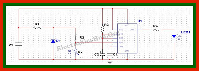
- V1 = 12 V
- R1 = 38 Ohms
- D1= 4.7 V Zener diode, 1N4732
- R2 = 100 Ohms
- Rx = HEL-700 platinum RTD
- R3 = 10K
- C2 = 1uF
- C1= 0.01 uF
- LED = 5V, Green LED
- IC = 555 Timer
Air Flow Detection Circuit Design:
This circuit is designed to provide a constant current input to the RTD so that it is heated slightly at the beginning. The RTD selected here is a HEL-700 platinum RTD, which works at a maximum operating current of 2 mA. Here we are using a Zener Diode as a voltage regulator to provide a constant current to the RTD.
To design a Zener voltage regulator, we need to first select the Zener diode. Here, a Zener diode with Vz = 4.7V is selected. Since the input voltage is 12V and the required output current is 2mA, we select a load resistance of 100 Ohms, so that maximum current flows through the load and only a small amount of current flows through the RTD. The input resistance selected is given by (Vin-Vz)/(Iz+IL) and is equal to 38 Ohms. Here, a 38-ohm resistor is used as the input resistor.
The next step requires the design of a timer monostable multi vibrator. Here, the timer is used to provide biasing voltage to the LED, which is about 5V. The LED is required to glow as the voltage across the RTD decreases. Here we select a resistor of 10K and an electrolyte capacitor of 1uF. A ceramic capacitor of 0.01uF is used to connect the control pin to ground.
Air Flow Detector Circuit Operation:
This circuit is operated using a 12V battery. The battery voltage is regulated using the Zener diode, which produces a constant voltage. Initially, as current flows through the RTD, it gets heated up and its temperature increases, thereby increasing its resistance. Now, as the current is constant, the voltage across the resistance also tends to increase. When this voltage is applied to the trigger pin of the timer, it fails to trigger the timer, and the LED is in the off condition. Now, as air flows over the RTD, it starts cooling. This reduces the temperature of the device. As the temperature reduces, the resistance also reduces, and so does the voltage across the device. As this voltage reduces below a certain point, the timer gets triggered and the LED starts blinking. As the voltage falls further, indicating a A fall in temperature, the LED starts glowing with full intensity. This indicates the flow the air.
Theory Behind Air Flow Detector Circuit:
The basic theory behind this circuit involves knowledge about three basic parts- Voltage Regulator using Zener Diode, Resistance Temperature detector and a timer circuit.
Voltage Regulator using Zener Diode:
Zener diode is a simple PN junction diode operated in reverse bias condition. It basically works on the principle of breakdown – Avalanche and Zener. Zener breakdown occurs at a reverse bias voltage between 2V to 8V, when highly strong electric field intensity causes the electrons to break free from the atoms and form free electron hole pairs. The avalanche breakdown occurs above 8V, when high speed charge carriers cause disrupt of covalent bond due to collision, leading to formation of free electrons.
As can be seen by the characteristics, for a large variation in current through the diode, the voltage across the diode remains very small or constant. This unique feature is utilized in many applications by using a Zener diode as the voltage regulator.
Resistance Temperature Detector:
A resistance temperature detector, or RTD, is a metal resistor whose resistance changes with temperature. It is based on the fact that in metals, as temperature increases, the lattice vibrations increase. These vibrations cause collisions among the electrons. As collisions increase, the energy of the electrons decreases, causing a decrease in the flow of free electrons, leading to low conductivity. Thus, with an increase in temperature, the resistance increases. An RTD is constructed using platinum. At 0 degrees Celsius, the resistance of an RTD is about 100 Ohms.
555 Timer Multivibrator:
The multivibrator circuit is used to produce a pulsed output signal. It is triggered when a low-level signal is applied to the trigger pin of the IC. The 555 timer IC is an 8-pin IC, and the timing of the output signal is given by T=1.1 RC. To get detailed information about the 555 timer IC, read the post Understanding 555 Timer.
Applications of the Air Flow Detector Circuit:
This circuit can be used to detect the flow of air in various practical applications/areas, like a car engine, where it is required to estimate the amount of fuel needed by the engine. Apart from being used as an air flow detector, this circuit can also find its application as a temperature detector circuit. With slight modifications, this circuit can be used to control loads like a fan, based on temperature sensing. Here are some of the main applications….
- Computer CPU fan monitoring
- HVAC system diagnostics
- Cleanroom airflow alerts
- DIY electronics and IoT sensors
Limitations of the Air Flow Detector Circuit:
- Since Zener diode is being used, the efficiency of the circuit is affected. This is because loss in series resistor causes a decline in efficiency in case of heavy loads.
- The resistance temperature detector used is expensive and easily affected by shock and vibration.
Note: Also read the post – Mosquito Repellent Circuit
FAQs:
The circuit uses a heated thermistor whose resistance changes with temperature. When air flows over it, the thermistor cools down, altering its resistance. A comparator detects this change and triggers an output like an LED or buzzer to indicate airflow.
Yes. This circuit is ideal for detecting airflow from small fans, vents, or ducts. It can help monitor whether a fan is working properly or if airflow is blocked, making it useful in systems like CPU cooling or exhaust monitoring.
Alternatives include hot wire anemometers, MEMS airflow sensors, and pressure sensors. These offer higher accuracy but are typically more expensive and complex compared to thermistor-based circuits.
With proper enclosure and shielding, the circuit can be adapted for outdoor or industrial use. However, for high-precision or harsh environments, industrial-grade airflow sensors are recommended for reliability and durability.
Absolutely. The output of the airflow detector circuit (typically HIGH or LOW voltage) can be connected to a digital input pin on an Arduino or similar microcontroller. This allows for advanced features like data logging, automated alerts, or IoT integration.
Conclusion
An air flow detector circuit is a practical, low-cost solution to monitor airflow using simple components. While it’s not as precise as advanced flow sensors, it’s ideal for basic airflow monitoring, system diagnostics, and electronics projects where detecting the presence or absence of air movement is enough. We hope this guide will help you in getting a clear idea on this airflow detection circuit.
Still having any queries related to this topic? Feel free to share them with us in the comments section below. We will respond and resolve them promptly.

4 Responses
GOOD
Very good idea sir
What is the RTD ?
Resistance Temperature detector