A motion detector circuit typically employs a passive infrared (PIR) sensor or an ultrasonic sensor to detect movement in its vicinity. When motion is detected, the sensor output activates, triggering a response such as turning on a light or an alarm. These circuits are widely used in security systems, automatic lighting controls, and various automation projects. The design involves connecting the sensor to a control unit, which processes the signal and executes the desired action, often requiring minimal components for a basic setup.
Motion Detector Circuit
The Motion Detector Circuit is not only used as intruder alarm but also used in many applications like home automation system, energy efficiency system, etc. The motion detector will detect the motion of the people or objects and give the appropriate output according to the circuit.
In general, motion detector uses different types of sensors like Passive infrared sensor (which will detect the motion of the person using the person body heat), microwave sensor (Microwave sensor will detect the motion of person by measuring the change in frequency from the produced beam), ultrasonic sensor (It produces acoustic signals which will detect the motion of a person) etc. There are some motion detectors which will use different technology and include number of sensors (PIR, microwave sensor, ultrasonic sensor, etc.) to reduce the false triggering and increase the accuracy in motion detection.
Here is the simple and reliable circuit which uses IR sensor for transmitting the IR beam and photo transistor for receiving the IR beam. If there is any disturbance or interference in between the transmitting and receiving of the beam, it will justify that there is an intrusion and makes the alert through alarm. This is circuit is easy to construct and cost of circuit is very low when compared to normal motion detector.
Block Diagram of Motion Detector:
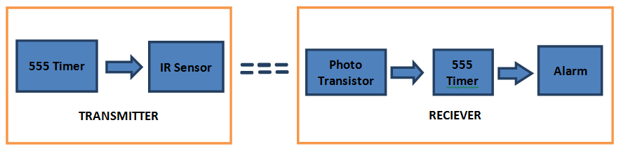
IR sensor will produce the high frequency beam which is projected on the photo transistor with the help of 555timer at the transmitter. When this high frequency beam has got any interruption, the photo transistor will trigger the 555 timer of receiver section and gives alert through the alarm.
Motion Detector Circuit Diagram:
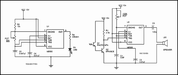
Motion Detector Circuit Explanation:
- The IR sensor will make the high frequency beam of 5 kHz with the help of 555timer which is set to astable multivibrator mode at the transmitter section.
- The IR sensor will produce the high frequency beam which is received by the photo resistor at the receiver section. This frequency will be in one phase when there is no interruption between the IR sensor and photo transistor. Total circuit will not give any output in this phase. When there is an interruption between IR sensor and photo transistor, the beam produced by the IR sensor will be in different phase. This different phase will be immediately detected by the photo resistor and make the 555 timer to give alarm through speaker.
- When there is no intrusion, the photo transistor will make the pin2 high of 555timer which is set in monostable mode, and there will be no output given in this configuration. When there is intrusion, the pin 2 of monostable timer is made low which will make the alarm to alert. The alarm time depends on the capacitor C1 and variable resistor POT.
Main Components in Motion Detector Circuit:
IR sensor: the main concept of IR sensor is to produce a beam of infrared light (whose wave wavelength is longer than visible rays and shorter than microwaves, in normal infrared wave length should be greater than 6µm). IR sensors are based on three different laws they are planks radiation law, Stephan Boltzmann law and Wien’s displacement law.
- Planks Radiation Law states that the energy of electromagnetic radiation is confined to indivisible packets (quanta), each of which has energy equal to the product of the Planck constant and the frequency of the radiation (planks constant = 6.62606957 × 10⁻³⁴ m2 kg /s).
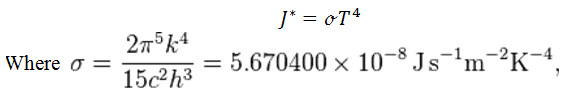
- Stephan Boltzmann Law states that total energy radiated per unit on a black body using all wavelengths per unit time J* is directly proportional to the fourth power of the black body’s thermodynamic temperature T:
- Wien’s Displacement Law: the wavelength of maximum emission of any body is inversely proportional to its absolute temperature (measured in Kelvin). As a result, as the temperature rises, the maximum (peak) of the radiant energy shifts toward the shorter wavelength (higher frequency and energy) end of the spectrum.
Peak intensity occurs at this wavelength ƛ =(0.0029 meter.K)/Temperature in Kelvin
In IR sensor the infrared source and transmission of infrared are two important parts. In infrared source, there are different sources like black body radiators, tungsten lamps, silicon carbide in IR sensors. They will use infrared wavelength LED as infrared source. In transmission media it will be different like air, optical fiber etc.
Photo Transistor: Photo transistors are the detectors of IR radiation or any photo radiation. They will convert this IR radiation into current or voltage.
Applications of Motion Detection:
- Motion detectors can be used as an intruder alarm in home, offices, banks, shopping malls etc.
- They can be used as counting machines, automatic light control etc.
- They can be used in energy efficient systems, home automation system and control systems.

17 Responses
its informative visit
hi,
I want to make a robot with the automatic path finder.
Can you help me with it?
Yeah a line follower car is a good example
This is a wonderful project. a friend did something similar a long time ago using 8051 microcontroller but iam happy to see it can be done with a 555 timer. however, which photo transistor should be used?
Its good but the circuit explanation is weak. More details of circuit build up and its working would be ideal.
guys does anyone have a list of components for this circuit
You can check the circuit diagram for components list
please can u upload a clear image of the circuit…components are not visible ..thank u
Sure We will upload it soon
Hey ,can u please upload the circuit in prosteus form to mkae it more clear…Really appreciate it
As all those who came before me; I would also like to see a list of components for this circuit, and an upload of a clear image of the circuits…components are not visible. I am retired and I’ve taken up learning more about electronics and circuits; so that I can better understand what is happening and build the as a hobby / pastime. Your explanation of this circuit above helps, but I’m a hands on person and need to build it for a better understanding of how it works.
can anybody please let me know what is the value of C1 and Q2
hey there…i want a complete circuit diagram for a car parking slot indicator using this motion sensor…please help it for my final project …i need help
In circuit diagram the values of components are not clear
This Website is unique. A vast collection of Circuits and different projects and tutorials i found here. Thanks
I would like to know how to disable temporarily in the microwave motion sensor or in PIR motion sensor to continuos on to trigger the alarm circuit. Thank you for the help.
5 kHz is not high frequency. It’s audible. Thanks for making the neighbourhood pets insane.