In this project, I will show you how to interface a 128X64 Graphical LCD with Arduino UNO. This particular LCD Module is based ST7920 LCD Controller. So, we will first see a little bit about the Graphical LCD Module and its LCD Controller ST7920.
Then we will see the steps for Interfacing the 128×64 Graphical LCD with Arduino UNO board and display some bitmap image.
Outline
ToggleInterfacing 128×64 Graphical LCD with Arduino
In the previous Arduino project, I have interfaced a Nokia 5110 LCD Module with Arduino. It is also a graphical LCD which can display some basic bitmap images and graphics. But the issue with Nokia 5110 LCD Module is its resolution.
At 84 x 48 pixels, the Nokia 5110 LCD can be used for implementing a menu-based user interface. Due to its small size, the resulting menu will be limited to 3 or 4 items per page.
If we want a bigger display with more real estate to work with, then the obvious choice is to go for the bigger and better 128×64 Graphical LCD Module.
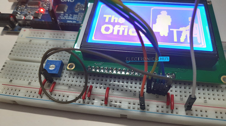
As a demonstration, after making all the hardware connections, I will display a bitmap image on the Graphical LCD Module. If you are interested in implementing a simple 16×2 Alpha-Numeric LCD with Arduino, then check out this tutorial.
A Brief Note on 128×64 Graphical LCD
At first glance, the 128×64 Graphical LCD Module seems like a bigger brother to the famous 16×2 LCD or 20×4 LCD Modules, with their similar construction and almost similar pin layout.
But there is a significant difference between those two. 16×2 or 20×4 LCDs are essentially character displays. They can only display alpha-numeric characters and some simple custom characters that are confined to a 5×8 matrix.
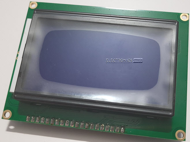
Coming to the 128×64 Graphical LCD, as the name suggests, it is a Graphical Display consisting of 128×64 i.e., 8192 individually controllable dots.
By using different combinations of pixels, we can basically display characters of various sizes. But the magic doesn’t end there. You can display images and graphics (small animations) as well. In a 128×64 LCD Module, there are 64 rows and 128 columns.
ST7920 LCD Controller
There are several versions of the Graphical LCD in the market. Even though the usage, application and implementations are almost identical, the main difference lies in the internal LCD Controller used to drive the dot matrix display.
Some of the commonly used LCD Controllers are KS0108, SSD1306, ST7920, SH1106, SSD1322, etc. The pin out of the final LCD Module might vary depending on the LCD Controller used. So, please verify the LCD Controller as well as the pin out before making a purchase.
The Graphical LCD Module I purchased consists of ST7920 Controller. It is manufactured by Sitronix and supports three types of bus interfaces i.e., 8-bit mode, 4-bit mode and Serial interface.
If you have used 16×2 LCD Display earlier, then you might be familiar with both 4-bit as well as 8-bit parallel interfaces. The serial interface is something new and we will explore this option in this project.
128×64 LCD Pinout
As I already mentioned, double-check with the manufacturer about the pinout of the Graphical LCD Module. The following table describes the pinout of the 128×64 LCD Module that I have.
| Pin Number | Pin Name | Pin Description |
| 1 | GND | Ground |
| 2 | VCC | Supply Voltage |
| 3 | VO | Contrast Adjust |
| 4 | RS | Register Select (CS in Serial) |
| 5 | RW | Read / Write Control (Serial Data In) |
| 6 | E | Enable (Serial CLK) |
| 7 – 14 | D0 – D7 | Data |
| 15 | PSB | Interface Selection (0: Serial, 1: 8-bit/4-bit Parallel) |
| 16 | NC | Not Connected |
| 17 | RST | Reset |
| 18 | VOUT | LCD Voltage Doubler Output |
| 19 | BLA | Backlight LED Anode |
| 20 | BLK | Backlight LED Cathode |
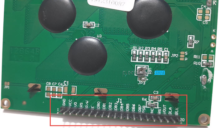
The following image shows the rear of the LCD with its pinout printed.
Interfacing 128×64 Graphical LCD with Arduino
Now that we have seen a little bit about the Graphical LCD and its controller ST7920, let us now proceed with interfacing the 128×64 Graphical LCD with Arduino. I will implement a simple circuit to demonstrate how easy it is to interface the LCD and Arduino using very few external components.
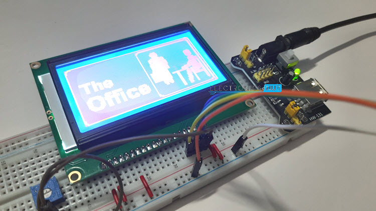
I will use the Serial Interface for Data Transfer and also display a Bitmap Image on the Graphical LCD.
Circuit Diagram
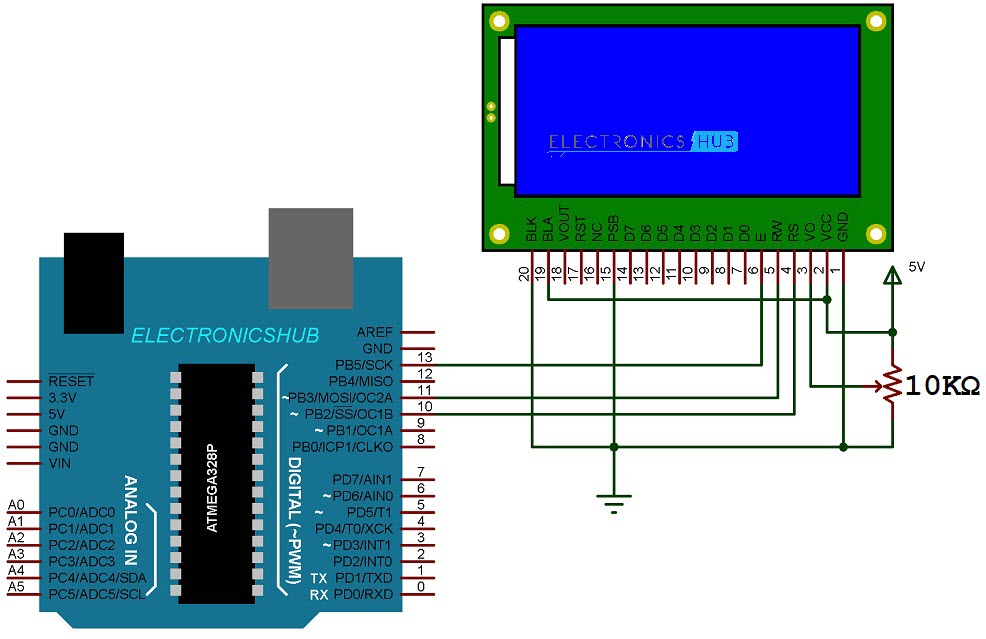
The following image shows the circuit diagram for Interfacing ST7920 Graphical LCD with Arduino UNO.
Components Required
- Arduino UNO
- 128×64 Graphical LCD Module
- 10KΩ Potentiometer
- Breadboard
- Breadboard Power Supply
- Connecting Wires
Hardware Connections
As mentioned earlier, there are three different ways in which you can interface the Graphical LCD with Arduino. They are:
- 4-bit Parallel Mode
- 8-bit Parallel Mode
- Serial Mode
In Serial Mode, we need only three pins for the actual data transfer. They are RS, RW and E. RS acts as Chip Select Pin in Serial Communication. RW and E acts as Serial Data IN and Serial CLK pins respectively.
So, connect the RS, RW and E of the LCD to Digital IO pins 10, 11 and 13 of Arduino UNO. Also, in order to select the Serial Interface Mode, the PCB pin must be connected to GND.
The remaining connections are similar to a traditional 16×2 LCD. VCC and GND are connected to 5V and ground of the power supply. VO is connected to the wiper of a 10KΩ POT while the other two terminals of the POT are connected to 5V and GND respectively.
In order to illuminate the LCD with backlight, connect the BLA to 5V and BLK to GND.
The colour of backlight in my LCD is blue. But White and Green are also common.
Generating HEX Code for Bitmap Image
Instead of displaying characters of different fonts (yes, there are libraries using which you can implement various fonts), I will straight away display an image in the form of bitmap. Before writing the code, you need to convert the bitmap image into byte arrays.
I have used the above “The Office” logo. Remember that the resolution of the 128×64 LCD is, well 128×64 pixels. So, the maximum image size should be 128×64. So, using Microsoft Paint, I have brought down the resolution of the above image to 128×64 pixels and also saved it as Monochrome Bitmap Image.
The next step is to convert this bitmap image into bytes array. I have tried several converter tools (both online and offline) but none of them were able to generate a code that is compatible with my setup.
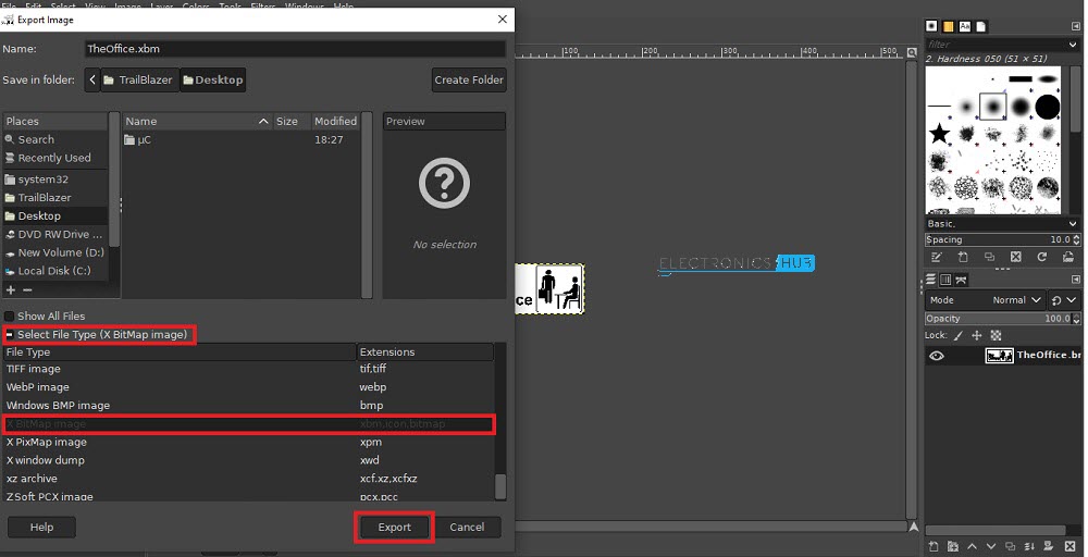
So, I have used the “GIMP” software. You can download GIMP from this link and install it. After installing, you can open the 128×64 Bitmap image in the GIMP software and export it as “X Bitmap Image”.
A .xbm file will be generated. It contains the HEX code for the selected 128×64 Bitmap Image. Open it with any text editor (like Notepad++) and make the following changes. The Array should be a static const unsigned char and append “PROGMEM” after the array name.
static const unsigned char myBitmap [] PROGMEM = {
0xf8, 0xff, 0xff, 0xff, 0xff, 0xff, 0xff, 0xff, 0xff, 0xff, 0xff, 0xff,
0xff, 0xff, 0xff, 0x3f, 0x3e, 0x00, 0x00, 0x00, 0x00, 0x00, 0x00, 0x00,
…..
0xff, 0xff, 0xff, 0x7f };
Code
Before writing the code, you need to download a special library called “U8g2”. In the Arduino IDE, go to Tools -> Manage Libraries… Search for “u8g2” and install the latest version. It is a complex library and its github page consists of all the necessary documentation.
The previously generated HEX code must be added into our code.
Conclusion
A simple project for interfacing the 128×64 Graphical LCD with Arduino is implemented here. Instead of displaying plain characters, I have displayed a bitmap image on the LCD to show its capability.
In the next project, I will show you how to design a simple Menu Display on the 128×64 Graphical LCD using Rotary Encoder.
Related Posts:
- Interfacing Nokia 5110 LCD with Arduino | Hookup Guide
- How to Design an Arduino Nokia 5110 LCD Menu?
- ESP32 Nokia 5110 LCD Display Tutorial | Display…
- Interfacing I2C LCD with ESP32 | ESP32 I2C LCD Tutorial
- How to Interface OLED Display with NodeMCU ESP8266?
- Interfacing Voltage Sensor with Arduino - Measure up…



4 Responses
wire.h will not work now with the Arduino. it has been replaced by wire_private.h.
congratulation who person think to develop Arduino,so i want to study about Arduino what can help me but i have A2 Certificate in mathematics physics and computer science thus thank you so much may God bless all member staff design Arduino.
This tutorial got me finding out most of the puzzle pieces I had missing.. :). Very nice work!
I however, got one question related to connecting an LCD I got… want to know if it can be interfaced the way you did here.. cause I’m not sure if it already has the controller built in (it has 3 horizontal and 4 vertical drivers) and a couple of simple IC-s, and it’s connection is a 14 pin FFC ribbon cable!
The model is: FH6-0635 MEDMMPU3W2F (monochrome display from an old Canon copier).
Thank you!
Hi Fisnik, Do you find finally some information about this screen?