In the previous tutorial, we have seen the concept of Serial Communication and how to transfer data between Arduino UNO and computer by using some predefined functions. In this tutorial, we will discuss about a new concept called PWM and how can this concept be used to control different devices like LEDs, motors etc.
For the purpose of the tutorial, we need to build a small circuit. The components required for this circuit are listed below.
- Arduino UNO [Buy Here]
- LED
- 1 KΩ Resistor
- 100 KΩ Potentiometer
- Breadboard (Prototyping board)
- Connecting wires
Arduino Pulse Width Modulation (PWM)
In this project, we will control the brightness of an LED connected to the Arduino UNO board with the help of PWM technique. The schematic required for the implementation of the project is shown in the below image.
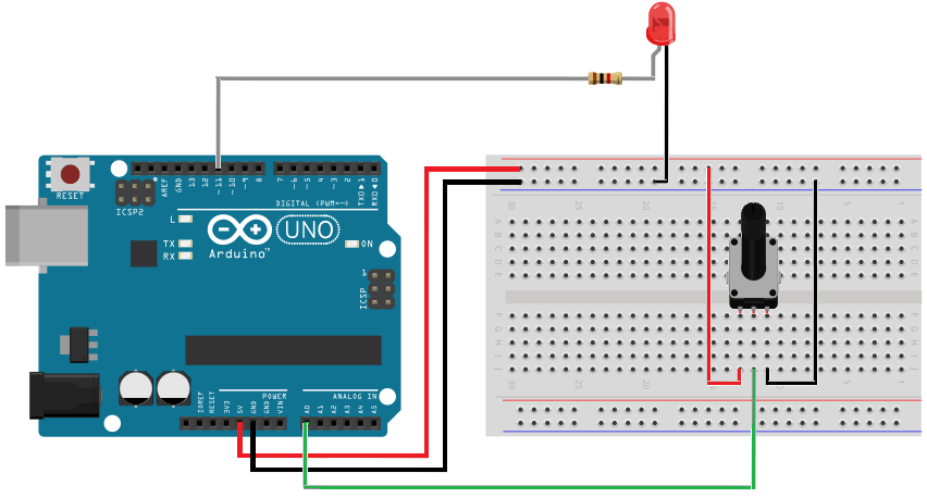
In this circuit, the anode of an LED must be connected to any of the PWM pin of the Arduino UNO. Hence, it is connected to pin 11 of the Arduino through a 1 KΩ current limiting resistor. The cathode of the LED is connected to ground on the breadboard.
The 5V supply and ground of the Arduino UNO are connected to positive and negative rail of the breadboard.
The end terminals of the potentiometer are connected to 5V and ground terminals on the breadboard respectively. The wiper terminal of the potentiometer must be connected to any of the analog input pin of the Arduino UNO.
By adjusting the potentiometer in either direction (clockwise or anti clockwise), a variable voltage i.e. between 0 to 5V will be given to the analog input pin of the Arduino. The analog to digital conversion feature of the Arduino UNO is used to convert these voltages to a digital range of 0 to 1023 (as Arduino has a 10 – bit ADC). With the help of this converted values, we can control the brightness of the LED.
Now that we have successfully designed the circuit, the next step is to write a suitable program for the circuit. Before going to the programming part, we need to get an idea about what PWM signal is.
Pulse Width Modulation
Pulse Width Modulation or simply PWM is a digital technique using which the amount of power delivered to a device can be varied. It provides a means of providing analog results with digital signals.
In PWM technique, a square wave is switched between on and off state. By changing the time the signal spend on “on” state versus the time the signal spends on “off” state, we can simulate a range of voltages between 0V and 5V. When this switching between on and off state is very fast, then the result is as if the output signal is at a stable voltage level between 0V and 5V.
One important term we need to discuss when dealing with PWM is Duty Cycle. It is defined as the ratio of the time for which the signal stays in HIGH state (on time) to that of the total time period of the signal (on time + off time).
In Arduino, there are 6 pins that are capable of generating such PWM signals. The following graph shows a comparison of different duty cycles and their corresponding voltage levels.
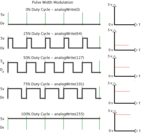
From the graph, it is clear that when the duty cycle is increased, the output voltage (or power delivered) is also increased. For 100% duty cycle, the voltage available is 5V and for 50% duty cycle, the voltage is 2.5V.
Coming to our tutorial, in order to generate a PWM signal, we need to learn about two functions in Arduino library: analogRead and analogWrite.
analogRead is a function which is used read the analog values from the analog pins of the Arduino. Arduino UNO board has 6 – channel, 10 – bit analog – to – digital converter (ADC). This means that the ADC in Arduino UNO will map the input voltages between 0 – 5V in to an integer value between 0 and 1023.
Hence, the analogRead function will return any value between 0 and 1023. The syntax of analogRead function is analogRead (analog pin no);
Since we are reading the analog voltages from the potentiometer at A0 pin, we need to write analogRead (A0); in the sketch. As it returns an integer value, a temporary variable of integer data type is created with it.
The next function is the analogWrite. It is a function which is used to set the duty cycle of the PWM signal for any given PWM pin.
The syntax of analogWrite function is analogWrite (PWM pin no, value);
The value indicates the duty cycle and must be a value between 0 (0V) and 255 (5V).
Coming to the actual sketch of the circuit for brightness control of the LED. The final sketch is shown in the following image.
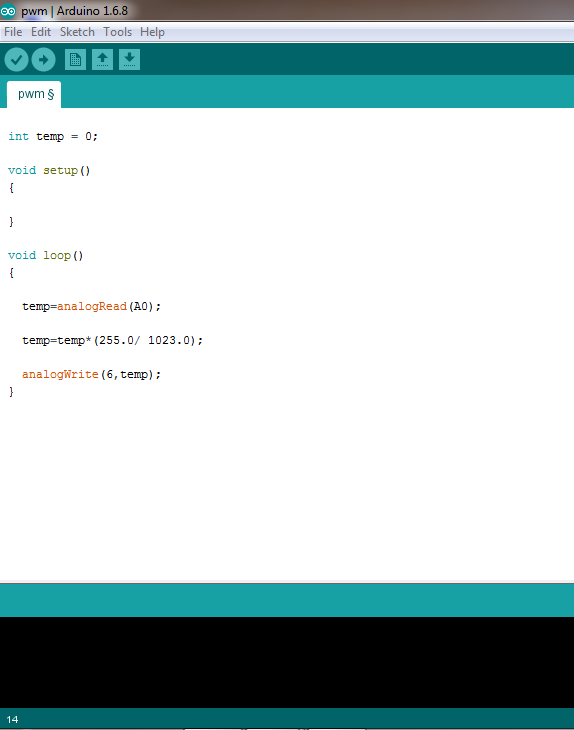
From the above sketch, we can easily understand that the value returned by the analogRead function is stored in the temp variable. This value will be used to control the duty cycle of the PWM signal using analogWrite function.
But the range of values accepted by the analogWrite function is between 0 and 255. Hence, we need to perform some mathematical calculations to put suitable value in the analogWrite function.
Finally, the calculated value is put in the analogWrite function along with the PWM pin to produce a PWM signal.
When the circuit is built and sketch is uploaded to the Arduino, we can see that by changing the position of the potentiometer, the brightness of the LED is also varied.

2 Responses
I have 10k potentiometer.
So, which resistor should i use with led?
And, is there any change in code
Please mention all…
Thanks in advance.
Thanks a lot¡ very easy to follow, really helped me out getting started¡
(I used a 10k Potentiometer, and a 10k resistance between LED and PIN 11. )