In this project, I will design a simple Frequency Divider Circuit using 555 Timer IC and CD4017 Counter IC.
What is Frequency Divider?
A Frequency Divider is a circuit that divides a given frequency by a factor of n, where n is an integer. For example, if the frequency of the Input signal to a Frequency Divider is FIN, then the frequency of the output generated by the Frequency Divider Circuit is given by
FOUT = FIN / n, where n is an integer.
Consider a divide by 10 Frequency Divider Circuit. This type of frequency divider circuit will produce an output signal with a frequency of one tenth of the input frequency.
Types of Frequency Dividers
Based on the application, Frequency Dividers can be designed for both Analog and Digital domains. Analog Frequency Dividers are used for very high frequency application but are very rarely used. They are further classified into Regenerative Dividers, Parametric Dividers and Harmonic Injection Dividers.
Coming to Digital Frequency Divider Circuit, they are easy to implement with the modern IC Technology and can work in the frequency range of up to tens of Giga Hertz.
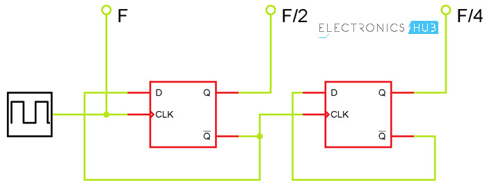
Digital Frequency Dividers are again classified into two types: Static and Dynamic. Static Frequency Divider Circuits are implemented using Bistable Cells i.e. Transistor based D Flip-flops.
A single D type Flip-flop will produce a divide by 2 frequency divider cell and using two D flip-flops, you can achieve a divide by 4 cell.
The Dynamic Frequency Dividers uses capacitances as storage elements and require a smaller number of transistors than the static counterparts.
Frequency Divider Circuit using 555 and 4017
In this project, we will not deal with GHz frequencies and complex dividers but rather a simple Frequency Divider Circuit using 555 Timer and CD4017 Counter. The aim of this circuit is to understand the concept of Frequency Dividers and build a simple circuit on your own.
Circuit Diagram of Frequency Divider Circuit
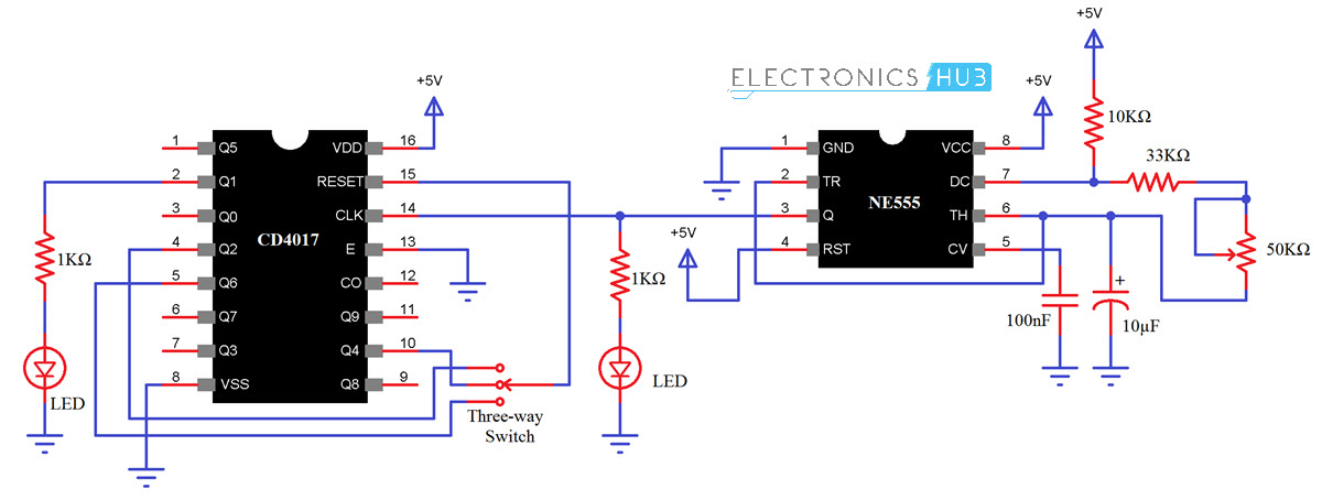
The circuit diagram of the Frequency Divider Circuit using 555 and 4017 is shown in the following image.
Components Required
- 555 Timer IC
- CD4017 Counter IC
- 10KΩ Resistor
- 33KΩ Resistor
- 1KΩ Resistor x 2
- 47KΩ Potentiometer
- 100nF Ceramic Capacitor (Code – 104)
- 10µF / 16V Capacitor
- LEDs x 2
- Three-way Switch (Single Pole – Triple Throw)
- Connecting Wires
- Mini Breadboard
- 5V Power Supply
Component Description
As you can see from the circuit diagram, the Frequency Divider Circuit has two important components: the 555 Timer IC and 4017 Counter IC.
555 IC
The 555 IC is one of the most frequently used integrated circuits. It is a simple Timer IC with a wide range of applications like pulse generation, Timing, oscillator etc.
In this project, I will be using the 555 Timer IC as a Pulse Generator or Clock Generator for the Frequency Division operation.
For more information on 555 IC, refer to UNDERSTANDING 555 TIMER.
4017 IC
The 4017 IC is a Decade Counter IC which produces 10 Decoded Outputs. It can be used as either Counter or Divider. In this project, I will be using this IC as the Frequency Divider IC.
For more information on 4017 IC, refer to CD 4017 IC-DECADE COUNTER.
Circuit Design
First, let me start the design of the circuit with pulse generation i.e. the 555 Timer IC. The VCC and RST Pins of 555 i.e. pins 8 and 4 are connected to +5V. Pins 2 and 6 are shorted and a 10µF Capacitor is connected between Pin 2 and GND.
A 10KΩ resistor is connected between pin 7 and VCC. A 33KΩ resistor and a 47KΩ POT are connected in series between Pins 7 and 6 (refer to the circuit diagram).
An LED with current limiting resistor is connected to Pin 3 of 555 and a 100nF capacitor Bypass capacitor is connected between Pin 5 and GND.
Now, coming to the Frequency Divider IC i.e. 4017, its pins 16 (VDD) 8 (VSS) and 13 (E) are connected to +5V, GND and GND respectively. An LED with current limiting resistor is connected to pin 2 (Q1).
Pin 14 is the clock input pin and is connected to Pin 3 of the 555 IC. Pin 15 of 4017 is the RST pin and is connected to input terminal of a three-way switch. The three output terminals of the switch are connected to Pins 4 (Q2), 10 (Q4) and 5 (Q6).
Working of the Frequency Divider Circuit
Let me divide the working of this circuit into two parts: Generation of the signal and division of its frequency.
The signal generation part is taken care by the 555 Timer IC, which is acting as an Astable Multivibrator. By varying the potentiometer, you can adjust the frequency of the pulse generated.
This pulse is given as an input to the 4017 IC as its clock signal. Now coming to the frequency division part, the RST (Pin 15) plays an important role here. In this circuit, you can connect the RST pin of 4017 to either of Q2, Q4 or Q6 pins with the help of the switch.
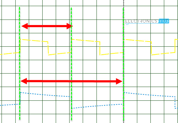
If the RST pin is connected to Q2, then the IC will reset on every second pulse of the clock input. Hence for every two instances of the clock signal (ON OFF ON OFF) there will be one instance of the output of 4017 (ON OFF). Hence, the frequency is divided by 2.
Similarly, when RST is connected to either Q4 or Q6, the frequency will be divided by either 4 or 6.
Applications
Frequency Divider Circuits or Frequency Dividers are an integral part of many communication and audio based systems like:
- Frequency Synthesizers
- Audio Equipment
- Radar and Satellite Communication
- Military Equipment
- RF Devices

One Response
nice project
can I get it’s conclusion