Flip flops will find their use in many of the fields in digital electronics. Flip flops are the main components of sequential circuits. Particularly, edge triggered flip flops are very resourceful devices that can be used in wide range of applications like storing of binary data, counter, transferring binary data from one location to other etc.
Applications of Flip Flops
Some of the most common applications of flip – flops are
- Counters
- Registers
- Frequency Divider circuits
- Data transfer
All these applications make use of the flip – flop’s clocked operation. Almost all of them come under the category of sequential circuits.
Counters
Counters are widely used in digital electronics and digital systems. They are used to count the number of events occurred in a specific interval of time. Mostly, a counter is used for counting the number of pulses entering at the input of a circuit in a specific time period.
In the terminology of digital electronics, a Counter is a sequential circuit that produces specific count sequence. It is an electronic device which is used to count the clock signals. Counters will have memory since they have to remember the past states of digital circuit and hence they consist of flip-flops in their structure.
Counters are classified into two types.
- Asynchronous counter
- Synchronous counter
Asynchronous counter
Asynchronous counter is also known as Ripple Counter. Asynchronous counter is formed by connecting complementing flip-flops together i.e. the first flip-flop is connected with the clock pulse input and the rest of the flip-flops are connected to the output of previous flip-flop.
We can create Complementing of flip-flops by using JK flip-flops and connecting their inputs together.
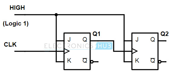

Here, the clock input is only connected for the first stage. The second stage is triggered by the output of the first stage because of propagation delay of flip flop. The transition of input clock pulse and Q1 output will never occur simultaneously. This is known as ‘Asynchronous operation of counters’. The output of the counter will toggle for the positive edge of the clock pulse because both the inputs are tied to HIGH (logic 1).
A ripple down counter can also be created by connecting the input of next flip-flop to the complimented output (Q’1). It will count from maximum to zero i.e. it acts as a down counter.
One more example of a counter is explained below.
Modulo – n – counter
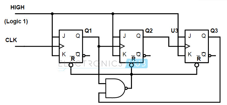
Modulo – n counter resets after a specified number is reached (after ‘n’). The number at which the reset should take place is given by NAND gate. Normal ripple counters are modified to act as modulo – n counters by using NAND gates. When the output of NAND gate is low, the flip flops will reset so does the counter output.
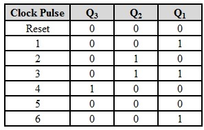
If we consider a modulo – 5 counter, the counter should reset when it reaches state 101. The inputs to the NAND gate should be connected to the outputs of the FF 1 and FF 3 i.e. Q1 and Q3. When the output of both these stages attains 1, then the output of the NAND gate is 0 and this resets the counter.
The logic diagram of a modulo – 5 counter is shown below.
Synchronous counter
In synchronous counters, all flip-flops are connected to the same clock signal and all flip-flops will trigger at the same time. These are also called as ‘Simultaneous counters’.
Example: 2 – Bit synchronous counter.
2 – Bit synchronous counter
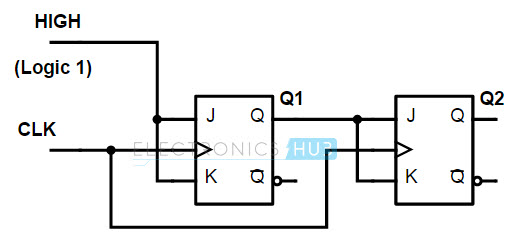
In this counter, both the flip flops are connected to the same clock pulse. The output of the first flip flop acts as the input of next flip flop.
Initially, the flip flops are assumed to be in reset state as their outputs are 0 i.e. Q1 = 0 and Q2 = 0. When we apply the first clock pulse, the first flip flop (FF 1) will toggle, as both the inputs of flip flop FF 1 are tied HIGH (logic 1). For the second clock pulse, both the flip flops will toggle because the inputs of both the flip flops FF 1 and FF 2 are at high. If we apply the third clock pulse, only first flip flop FF 1 will toggle because the input to the flip flop FF 2 is 0.

In case of a 3 – bit synchronous counter, the inputs to the third flip flop is connected to an AND gate that is fed by the outputs of first and second flip flops (Q1 and Q2) i.e. the inputs to the third flip flop are tied to the product Q1Q2. Similarly, in case of a 4 – bit synchronous counter, the inputs of the fourth flip flop should be tied to product Q1Q2Q3.
There are many more types of counters we use, like
- Ring counter
- BCD counter
- Decade counter
- Up/Down counter
- Frequency counter
Applications of Counters
Counters are used as Digital clocks, Frequency counters, Binary counters etc.
Registers
Flip flops can store a single bit of data i.e. 1 or 0. Registers are used to store multiple bits of data. So flip flops are used to design Registers. According to digital electronics, a Register is a device which is used to store the information. As a single flip flop is allowed for 1 – bit storage, n flip flops are connected in an order to store n bits of data. For example, if a computer is to store 16 bit data, then it needs a set of 16 flip flops. The input and outputs of a register may be serial or parallel based on the requirement. The series of data bits are stored by registers is called “Byte” or “Word”.
When a number of flip flops are connected in series, this arrangement is called a Register. The stored information can be transferred within the registers; these are called as ‘Shift Registers’.
Asynchronous and Synchronous registers:
Shift registers are made up of flip-flops and their operation is depends up on the state of flip-flops.
The registers which will work depending up on the asynchronous triggering are called “Asynchronous shift registers”.
Similarly, the shift registers which will change their state only when they are triggered by clock pulse are called “Synchronous shift registers”.
Shift registers are of several types, they are
- Shift left register.
- Shift right register.
- Shift around register.
- Bi directional shift registers.
- Universal shift registers
Frequency Division
As the name implies, the frequency divider circuits are used to produce the digital signal output exactly half the input frequency. The frequency divider circuits are generally used in design of asynchronous counters.
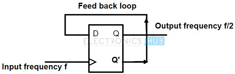
The process of dividing or reducing the output frequency to half of its input signal frequency is called “Frequency division”.
This means if we process an input signal of frequency 160k Hz, then the frequency divider circuit will provide the output of 80k Hz.
Data Transfer
“Data transfer” is the process of transferring the data from one register to another register.
In general, the shift registers perform this type of operations. Data can be transferred by using flip-flops, in two ways. They are
- Serial data transfer.
- Parallel data transfer

2 Responses
Good. Work
Good. Very helpful