In this tutorial, we will learn how to use PWM in ESP32 SoC. Using PWM in ESP32, you can control the brightness of LED, set the position of a Servo Motor and adjust the speed of a DC Motor. This ESP32 PWM Tutorial contains all the important information for configuring PWM in ESP32.
A Brief Note on ESP32 PWM
The ESP32 SoC is fully loaded with very useful peripherals and PWM is one of them. Yes. There is a dedicated hardware block for PWM in the silicon of ESP32. Pulse Width Modulation or PWM in short is an established and widely used techniques for power delivery.
You can use ESP32’s PWM to drive LEDs, motors (normal DC Motors as well as Brushless Motors) and smart lights. The PWM Controller in ESP32 consists of two main sub-modules: LED Control or LEDC Peripheral and Motor Control Pulse Width Modulator or MCPWM Peripheral.
Even though we will be limiting our demonstration of PWM in ESP32 to fading an LED, it is good to know about the Motor Control PWM (MCPWM) block in ESP32, with input capture modules.
If you ever worked with Brushless DC (BLDC) Motors, you will realize the importance of sensing the position of the rotor (using Hall Effect Sensors) for precise speed control.
ESP32 LED PWM Controller (LEDC)
The LEDC Peripheral of ESP32 consists of 16 PWM Channels capable of generating independent waveforms, mainly for RGB LED Control, but can also be used for other purposes as well.
There are a couple of interesting points about LED PWM Controller in ESP32 that you should be aware of.
- 16 independent PWM Channels, divided into group of two with 8 channels per group.
- Programmable resolution between 1-bit and 16-bits.
- Frequency of the PWM wave depends on the resolution of PWM.
- Automatically increases / decreases duty cycle without processor intervention.
Configure PWM Channels of ESP32
Do you remember ‘analogWrite()’ function in Arduino programming? It is the function responsible for generating PWM in Arduino UNO (and other ‘Arduino’ boards).
Since, pretty much every thing in LED PWM of ESP32 is user configurable (channel, resolution and frequency), instead of using ‘analogWrite()’ function, we will be using a different (and dedicated) set of functions to configure PWM in ESP32.
Here is a list of all the LEDC APIs exposed by the driver. These functions are written for Arduino IDE port of ESP32.
- ledcSetup(channel, frequency, resolution_bits);
- ledcAttachPin(pin, channel);
- ledcWrite(channel, dutycycle);
- ledcRead(channel);
- ledcWriteTone(channel, frequency);
- ledcWriteNote(channel, note, octave);
- ledcReadFreq(channel);
- ledcDetachPin(pin);
Of the 8 functions, we will be focusing on the first three, as they are more useful (and the minimum required) for generating PWM.
Some important points to remember while configuring PWM Channel in ESP32:
- As there are 16 PWM channels, the ‘channel’ argument takes any value between 0 and 15.
- Next is the frequency of the PWM signal. You can set the frequency as per your requirements like 1 KHz, 5 KHz, 8 KHz, and 10 KHz.
- The resolution of the PWM is also configurable and ESP32 PWM can be programmed anywhere between 1 bit to 16 bit resolution.
- PWM frequency and resolution are inversely proportional and is dependent on the clock source. So, be careful when selecting the values for frequency and resolution.
- Finally, assign a GPIO pin for PWM Output. You can assign any GPIO Pin but be careful when assigning (do not use already used GPIO pins like UART, SPI, etc.).
The following table shows a few commonly used PWM frequencies and resolutions.
|
Clock Source for LEDC |
LEDC PWM Frequency |
PWM Resolution |
|
80 MHz APB_CLK |
1 KHz | 16 bit |
| 80 MHz APB_CLK | 5 KHz |
14 bit |
|
80 MHz APB_CLK |
10 KHz | 13 bit |
| 8 MHz RTC8M_CLK | 1 KHz |
13 bit |
|
8 MHz RTC8M_CLK |
8 KHz | 10 bit |
| 1 MHz REF_TICK | 1 KHz |
10 bit |
LED Fading using PWM in ESP32
With all the necessary information on PWM in ESP32 being laid out, we can now proceed to implementing our first project of fading an LED using ESP32 PWM. It is a very simple project where the brightness of an LED connected to a GPIO Pin of ESP32 will gradually increase and decrease repeatedly.[ESP32 Projects for Beginners]
This project is more about understanding the LEDC functions: ledcSetup, ledcAttachPin and ledcWrite and how to generate PWM in ESP32 than the fading LED itself.
Components Required
- ESP32 DevKit Development Board
- 3 x 5mm LED
- 220Ω Resistor
- 3 x 5KΩ Potentiometers
- Breadboard
- Connecting Wires
- Micro-USB Cable
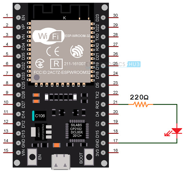
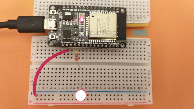
Circuit Diagram
The following image shows the connection for fading an LED using ESP32 PWM Controller.
Code
You can use any GPIO Pin to output the PWM Signal. So, I am using GPIO 16, which is also the UART2 RX Pin. Next, we have to setup the LEDC Channel using ‘ledcSetup’ function. The first argument is the channel. Any value between 0 and 15 can be given as channel.
Next argument is the frequency. You can provide any frequency but as a convenience, I will set the frequency as 5 KHz. Also, you have to set the resolution of the PWM. This value must be a number between 1 and 16. I went with 10-bit resolution.
For the rest of the settings, refer to the following code, where I commented the important lines.
NOTE: You can attach multiple GPIO pins to the same LEDC PWM Channel. If you do so, all the GPIO pins will share the properties of the channel (resolution and frequency).
ESP32 PWM with ADC
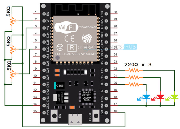
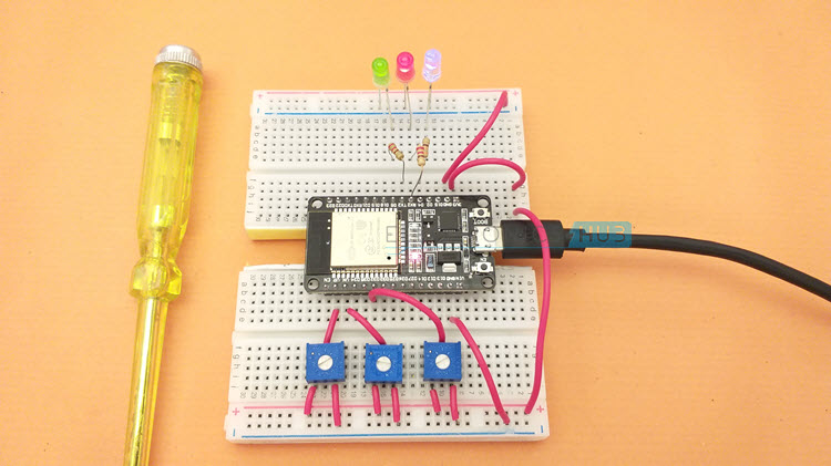
One of the important features of PWM in ESP32 is all the 16 channels can be configured independently i.e., each channel can have its own resolution and frequency. To demonstrate this, let us make use of the ADC peripheral and adjust the dutycycle of three different LEDC PWM channels independently by turning a potentiometer.
Three 5KΩ Potentiometers are connected to three ADC Input pins of ESP32. Based on the output of the ADC, we will set the dutycycle of three PWM Channels, which are configured with different parameters.
For easy understanding, I connected three LEDs: RED, GREEN and BLUE to three GPIO Pins. These three GPIO Pins are attached to three different LEDC PWM Channels and each channel is initialized with its own frequency and resolution.
|
LED |
GPIO Pin | PWM Channel | PWM Frequency | PWM Resolution |
| RED | GPIO 16 | 0 | 5000 (5 KHz) |
12 |
|
GREEN |
GPIO 17 | 2 | 8000 (8 KHz) | 13 |
| BLUE | GPIO 4 | 4 | 10000 (10 KHz) |
14 |
Another important point to remember is the resolution of ADC of ESP32 is 12-bit. So, we have to map this to the PWM resolution carefully, to get the full range of control.
Circuit Diagram
The following image shows the connections for adjusting the dutycycle of PWM Channels using ADC (potentiometers).
Code
Conclusion
A complete tutorial on ESP32 PWM peripheral. You learned how to use PWM in ESP32 to fade an LED, how to configure the PWM Channel, set the frequency and resolution. You also learned how PWM Channels in ESP32 can be configured independently.

3 Responses
Can you please show the needed header files to access those ESP32 functions?
There is no header file required. However this tutorial is base on an obsolete version of the API. If you want to use these functions you should find a tutorial based on the current release of the API (Version 3 at least).
Thank you for the great tutorial. Helped a lot. Just have one question. If I would like to controle four identical LEDs with my esp32 is it necessary to set different channel and frequency for each led or are the LEDs already separated because of the different gpio pins? I guess I only have to change the parameters when I use different devices. Correct?