In this project, I will show you how to design and build a simple Car Speed Detector circuit using Arduino UNO and IR Sensors. This Arduino Car Speed Detector project can be used to detect speed of a moving car.
Introduction
There are definite rules laid out by authorities about driving cars on roads. The most common rule in any country is speed limit in certain roads i.e. you will be in violation of the law if your car speed exceeds this limit.
In order to detect the speed of a moving car, the patrolling officers usually depend on a handheld gun that works on Radar Technology or Lidar Technology. This is a tedious process as the officer has to manually check for over speeding for each vehicle.
What if the Car Speed Detection is made automatic? A simple automatic detection of speed of a vehicle is designed in Arduino Car Speed Detector project, where you can place the system in one place and view the results instantly without any human intervention.
Principle of the Project
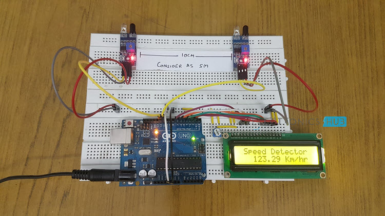
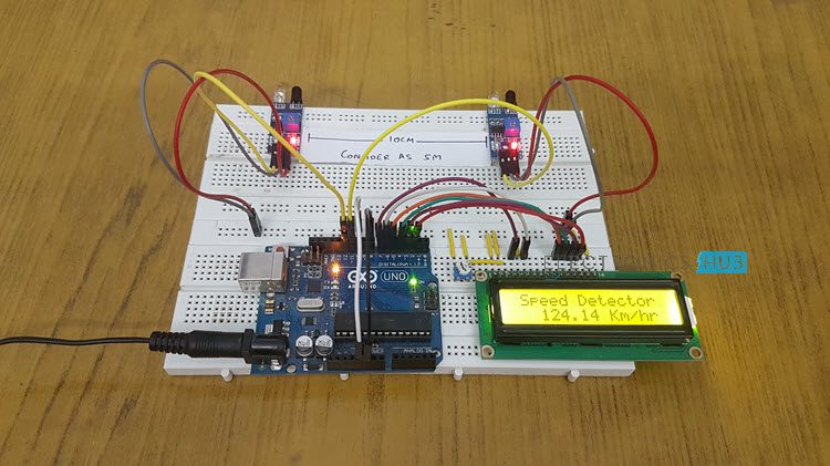
IR Sensors are the main part of the project that detect the speed of a car. Practically, you can implement the setup of IR Sensors in many ways but in this project, I have used two reflective type IR Sensors and placed them 10cm apart.
When a car travelling reaches the first sensor, the IR Sensor gets activated. From this moment onward, a timer is initiated and will continue to keep time until the car reaches the second IR Sensor.
By simulating the distance between the two sensors to be 5 meters, you can calculate the speed at which the car travelled from IR Sensor 1 to IR Sensor 2 as you already know the time of travel.
All the calculations and data gathering are done by Arduino and the final result is displayed on a 16X2 LCD Module.
Circuit Diagram of Arduino Car Speed Detector
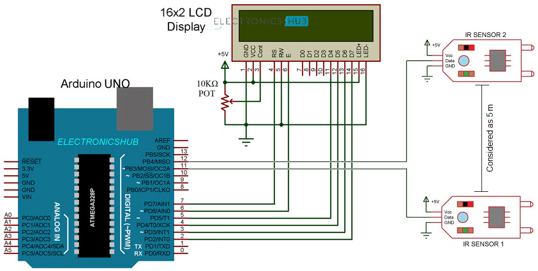
The following image shows the circuit diagram of the Arduino car speed detector project.
Components Required
- Arduino UNO
- IR Sensors x 2
- 16X2 LCD Display Module
- Breadboard
- Connecting Wires
- Power Supply
A Brief Note on IR Sensor
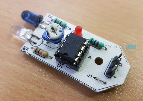
First of all, I have used two digital IR Sensors, which consists of an IR Transmitter (IR LED), an IR Receiver (Photo Diode), a Comparator IC and a few supporting components. The IR Transmitter and Receiver Pair are placed side-by-side so that they form a Reflective Type IR Sensor.
In this type, the IR Transmitter continuously emits Infrared radiations and if there is no object in front of the sensor, none of the Infrared radiation gets reflected back to the IR Receiver.
But if there is an object in front of the sensor, some of the infrared radiation hits the object and gets reflected back. This reflected radiation falls on the IR Receiver, which means that the sensor has detected the object.
Some IR Sensors has the option to produce both Analog and Digital Outputs but the module I have used has only Digital Output i.e. the output is HIGH when an object is detected and LOW when there is no object.
Circuit Design
The Digital OUT of the first IR Sensor is connected to Pin 11 of Arduino and the Digital OUT of the second IR Sensor is connected to Pin 12 of Arduino. Both the IR Sensors are provided with necessary power supply connections.
In order to view the car speed details, I have used a 16×2 LCD. Its data pins i.e. D4 – D7 are connected to Digital I/O pins 5 – 2. The RS and E pins of LCD are connected to pins 7 and 6 of Arduino. Rest of the connections are mentioned in the circuit diagram.
Code
How to operate Arduino Car Speed Detector Project?
- Make all the necessary connections with respect to the circuit diagram and upload the code to Arduino.
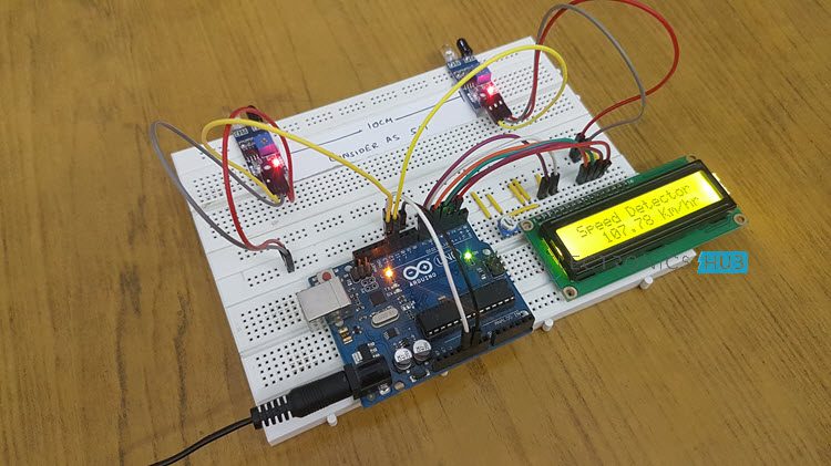
- Place the two IR Sensors on the edge of the breadboard so that the distance between them is approximately 10 centimeters.
- Simulate a car movement in front of the sensors either by using your hands or a toy car.
- Arduino calculates the speed and displays the result on the 16×2 LCD.
Working
The working of the Arduino based car speed detector project is very simple. Arduino continuously reads the inputs from the IR Sensors. When a car moving in front of the setup reaches the first sensor, Arduino becomes alert and capture a time stamp the moment the car leaves the first IR Sensor.
Another time stamp is recorded when the car reaches the second IR Sensor. Millis() function of Arduino used for capturing the time stamps.
Arduino then calculates the velocity by assuming the distance as 5 meters between the two IR Sensor and displays the result in kilometers per hour on the 16×2 LCD Display
Applications
- Helps in capturing speed of vehicles without any human involvement.
- This project can also be used as traffic logger, traffic counter and few other traffic related applications.

3 Responses
Nicely explained. I like the concept and how simple it is, at least the way you explained it. LOL
However i do have following questions
1. How well does it work in bright summer sunny days and similiar at dark winter nights?
2. How accurate is the reported speed ?
3. What is the max distance limitation of the IR sensor..
Sorry loaded questions your answers will help tremedously.
thanks
Hey, fantastic post and thank you for sharing! I was wondering if you know how to upload the speed data to a smart phone using a WIFI Module… if that’s even possible?
Let me know and thanks so much again for the great post!
Best,
Elijah
I want this model without using aurdino