The use of personal vehicles is very common now a days and a result, the number of vehicles on the roads are exponentially increasing. Roads without any supervision or guidance can lead in to traffic congestions and accidents.
Traffic Lights or Traffic Signals are signalling devices that are used to control the flow of traffic. Generally, they are positioned at junctions, intersections, ‘X’ roads, pedestrian crossings etc. and alternate the priority of who has to wait and who has to go.
The traffic lights will provide instructions to the users (drivers and pedestrians) by displaying lights of standard color. The three colors used in traffic lights are Red, Yellow and Green.
The system must be used to control the traffic lights for smooth and safe movement of traffic. These control systems consists of electro mechanical controllers with clockwork mechanisms or modern solid state computerised systems with easy setup and maintenance.
Arduino Traffic Light Controller
In this project, an Arduino based Traffic Light Controller system is designed. It is a simple implementation of traffic lights system but can be extended to a real time system with programmable timings, pedestrian lighting etc.
Circuit Diagram
Components
- Arduino UNO [Buy Here]
- 1KΩ Resistor X 12
- Red LEDs X 4
- Yellow LEDs X 4
- Green LEDs X 4
- Connecting wires
- Prototyping board
- Power adapter
Component Description
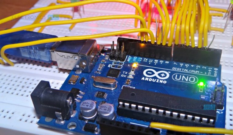
Arduino UNO: The main part of the Traffic Light Controller is the controller itself. Arduino UNO will serve the purpose in this project to handle all the switching of the LEDs and controlling their timings.
LEDs: The LEDs used in the project are basic 5mm LEDs of Red, Yellow and Green colors. The maximum current that can be allowed through these LEDs (Red, Yellow and Green in particular) is 20mA. (Foe Blue LED, the maximum current can be up to 30mA).
Circuit Design
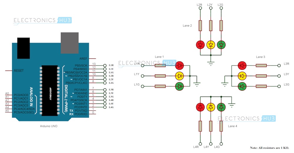
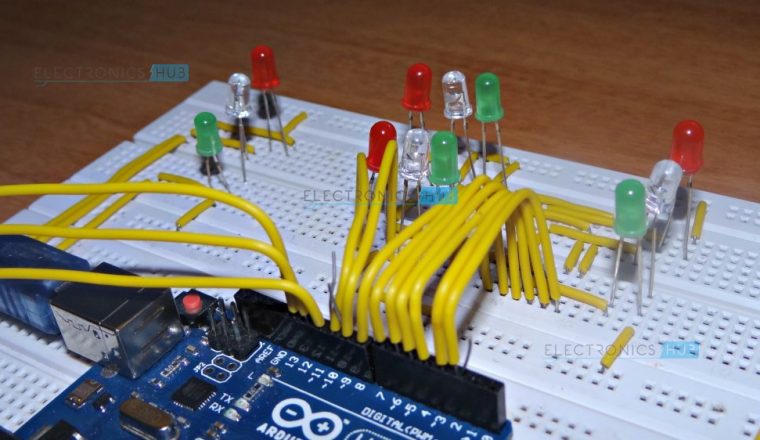
Since the project is a traffic light controller, the circuit consists of many LEDs (12 as a matter of fact) as we are implementing traffic lights at a 4 way intersection. The project is a simple representation of traffic light controller and hence no other extra components are used.
We need three LEDs of Red, Yellow and Green colors at each intersection. The intersection is divided in to four lanes: Lane1, Lane 2 Lane 3 and Lane 4.
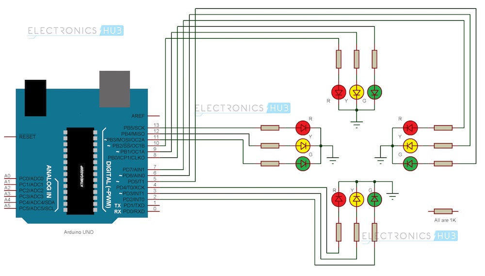
All the LEDs are connected to the Arduino UNO’s digital I/O pins through respective current limiting resistors of 1KΩ.
All the connections are made as per the circuit diagram. The complete wiring diagram of the circuit is shown below.
Note: In the practical implementation of the project, we did not use the current limiting resistors as the current from each digital I/O pin of the Arduino UNO is only 20mA. This small current will not burn the LED. But it is advised to use the current limiting resistors of at least 220 Ω in series with each LED.
Also note that Arduino UNO in this project acts as source of current for all the LED i.e. it provides the necessary current to turn ON the LED. Hence, a reliable power supply (like a DC adapter) to power the Arduino UNO must be used.
Working of the Traffic Light Controller Project
The real time traffic light controller is a complex piece of equipment which consists of power cabinet, main controller or processor, relays, control panel with switches or keys, communication ports etc.
In this project, a simple traffic light system for a 4 way intersection is implemented using Arduino UNO. Although it is not the ideal implementation for real life scenarios, it gives an idea of the process behind the traffic light control system
The aim of the project is to implement a simple traffic light controller using Arduino UNO, where the traffic is controlled in a pre-defined timing system. The working of the project is very simple and is explained below.
Consider the following gif image showing a loop of traffic light operations. The project is also implemented in the same manner.
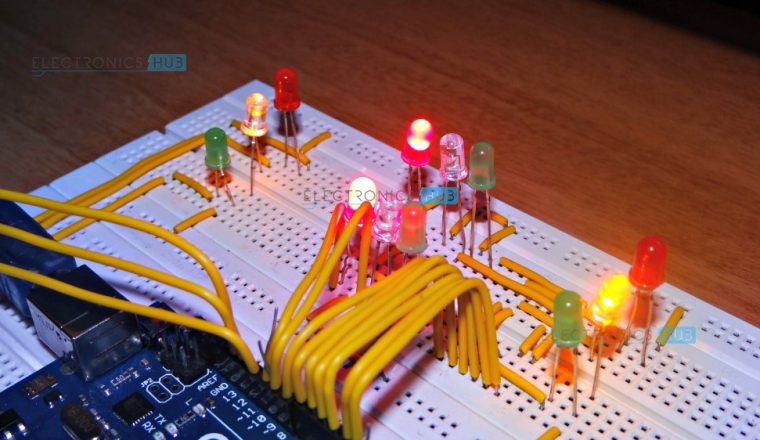
In that, first the Lane 1 gets its Green light turned. Hence, in all the other Lanes, their corresponding Red lights are turned on. After a time delay of predefined time say 5 seconds, the Green light in the Lane 3 must be turned on and the Green light in the Lane 1 must be turned off.
As a warning indicator, the Yellow light in Lane 1 is tuned on indicating that the red light is about to light up. Similarly, the yellow light in the Lane 3 is also turned as an indication that the green light about to be turned on.
The yellow lights in Lanes 1 and 3 are turned for a small duration say 2 seconds after with the red light in the Lane 1 is turned on and green light in Lane 3 is also turned on.
The green light in Lane 3 is also turned on for a predefined time and the process moves forward to Lane 4 and finally Lane 2.
The system then loops back to Lane 1 where the process mentioned above will be repeated all over again.
Note: The project implemented here doesn’t include the pedestrian crossing and pedestrian signaling in to consideration.
Limitations
- The project is not suitable for actual implementation but just a demonstration of the process behind the system.
- Real time traffic light controller systems are generally run time programmable i.e. the operator (usually a policeman) can change the timings of each lane as per the intensity of the traffic in each lane.
- There will also be a provision for either manual operation or pre-programmed operation.
Applications
- A simple traffic light controller is implemented in this project with a real chance of expansion.
- An external memory can be interface with the main controller so that the timings are not fixed during its programming but rather can be programmed during operation.
- An efficient traffic light controller system will include a pedestrian signaling system.

20 Responses
Please send me the presentation or PPT file of this project
You can do this yourself relatively quickly 🙂 take a look at something like Fritzing for circuit and Arduino graphics.
thank you code working but LED light in disorder
Double check your code and wiring. Most likely you have some connections switched around.
Hi, We will implement the project and update it as early as possible. Stay tuned.
my fyp project is smart traffic light for ambulance. I plan to add RFID sensor to this project. Mean if the traffic light at ambulance path is RED, RFID sensor will turn the traffic light to the green. can i just use the same coding and add coding for RFID only?
Hey syaamil, my fyp is same as yours. Can you provide me the code of your project?
Please send us the same program to be implemented with the ultrasonic sensor.
This worked great for me – better than the other two examples I tried that I found on the web.
Any thoughts on how to rewire to push more LEDs? I want to be able to drive a total of 16 sets of traffic lights (four intersections). They will still use the same program, so each intersection will be in sync with the others (essentially, power 4 LEDs everywhere you show one), but I fear I may overload the I/O pins since they’ll be pushin 80ma each at any given time – 320ma for the whole board (I think I’m under for the board but over for each pin). Any thoughts other than relays? Are there relays that run off of such low voltage and current?
A relay or similar is the ideal way to control a higher current load without the risk of damaging the Arduino microcontroller. It’s certainly feasible to trigger a relay with an Arduino digital output pin, but you might also consider using a transistor or similar semiconductor switch instead.
I am designing an HO scale layout for trolley, streetcar, rapid transit cars.,It will have subway, street, & elevated tracks. I will need a traffic controller for street traffic, 4 light for . 10-12 intersections probably four – six N – S with N – S,, E – W with N – S sequencing one intersection after another, time cycles, Streetcar can interrupt cycle. Pedestrian has on demand cycle.
One and two lane streetcar street level. Two lane Elevated that loops through the subway, up to ground level on ground on elevated.
Would you suggest a light sensor looking up through the rails? Photoresistor, LM393. Can add light sources in the subway, Street lights for ground level, lighting on elevated trestle so night operation, signals can be used.
My personal preference is neodymium magnets on the underside of the rolling stock to trigger a Hall effect sensor under the track, as trying something similar with light sensors proved to be too sensitive to false triggering. These days with Arduino, RFID could be a viable option also. This gives you the added benefit of knowing which train is passing over the sensor, as well as when.
Got some problem with the flow of the light…..normally traffic light is green to yellow and then turn to red…but from red to green no need yellow then green…
If the lights are going from red straight to green and not yellow first, double check your code; it’s possible you missed something out. You can modify the light progression by adjusting the sequence of digitalWrites in the loop.
Hello I changed the code where there is no yellow when switching from red to green;
int Lane1[] = {13,12,11}; // Lane 1 Red, Yellow and Green
int Lane2[] = {10,9,8};// Lane 2 Red, Yellow and Green
int Lane3[] = {7,6,5};// Lane 3 Red, Yellow and Green
int Lane4[] = {4,3,2};// Lane 4 Red, Yellow and Green
void setup()
{
for (int i = 0; i < 3; i++)
{
pinMode(Lane1[i], OUTPUT);
pinMode(Lane2[i], OUTPUT);
pinMode(Lane3[i], OUTPUT);
pinMode(Lane4[i], OUTPUT);
}
for (int i = 0; i < 3; i++)
{
digitalWrite(Lane1[i], LOW);
digitalWrite(Lane2[i], LOW);
digitalWrite(Lane3[i], LOW);
digitalWrite(Lane4[i], LOW);
}
}
void loop()
{
digitalWrite(Lane1[2], HIGH);
digitalWrite(Lane3[0], HIGH);
digitalWrite(Lane4[0], HIGH);
digitalWrite(Lane2[0], HIGH);
delay(7000);
digitalWrite(Lane1[2], LOW);
digitalWrite(Lane3[0], HIGH);
digitalWrite(Lane1[1], HIGH);
delay(3000);
digitalWrite(Lane1[1], LOW);
digitalWrite(Lane3[0], LOW);
digitalWrite(Lane1[0], HIGH);
digitalWrite(Lane3[2], HIGH);
delay(7000);
digitalWrite(Lane3[2], LOW);
digitalWrite(Lane4[0], HIGH);
digitalWrite(Lane3[1], HIGH);
delay(3000);
digitalWrite(Lane3[1], LOW);
digitalWrite(Lane4[0], LOW);
digitalWrite(Lane3[0], HIGH);
digitalWrite(Lane4[2], HIGH);
delay(7000);
digitalWrite(Lane4[2], LOW);
digitalWrite(Lane2[0], HIGH);
digitalWrite(Lane4[1], HIGH);
delay(3000);
digitalWrite(Lane4[1], LOW);
digitalWrite(Lane2[0], LOW);
digitalWrite(Lane4[0], HIGH);
digitalWrite(Lane2[2], HIGH);
delay(7000);
digitalWrite(Lane1[0], HIGH);
digitalWrite(Lane2[2], LOW);
digitalWrite(Lane2[1], HIGH);
delay(3000);
digitalWrite(Lane2[1], LOW);
digitalWrite(Lane1[0], LOW);
}
hi,, wt software (c,c++,java) should use to run this program
arduino software
So you just want a single red, yellow and green LED? You can do that easily by removing three sets of LEDs and resistors and amending the code in the loop to only change the three remaining pins.
thank you it is really helped me
how to make this project into less power consumption ? can u give an idea