In this article we will take a look at Current Amplifiers, Current Buffers and Current Followers in detail.
Current Amplifier
Introduction
A Current amplifier is an electronic circuit that increases the magnitude of current of an input signal by a fixed multiple, and feeds it to the succeeding circuit/device. This process is termed as current amplification of an input signal.
The input can either be a constant signal or a time varying waveform. Ideally, during this process of current amplification, the current amplifier will keep the voltage component of the input signal unchanged. Below is the block diagram of a typical current amplifier.
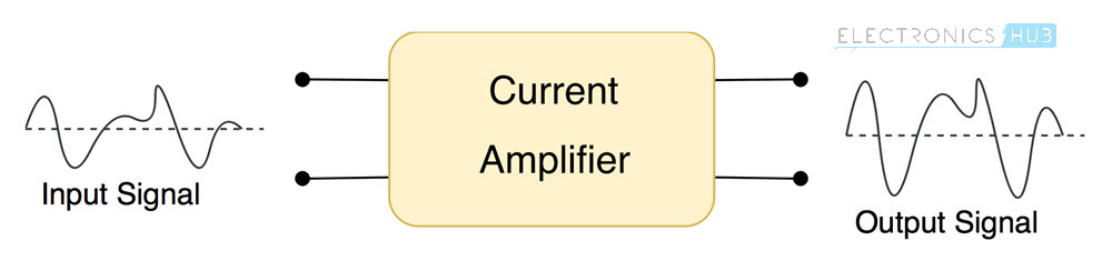
The waveforms at the input and output terminals denote the magnitude of current with respect to time. Notice that the entire waveform is stretched (increased) at the output by a fixed factor.
Gain of a Current Amplifier
In electronics, “Gain” is the technical term used for rating the amplifying capability of an amplifier. And because a current amplifier transforms only the current component of the input signal, its gain is based on how much it increases the current of output signal with respect to the input signal.
Mathematically, the gain of a current amplifier is the ratio between the magnitude of current flowing through its output terminals, to the magnitude of current of the input signal. It is denoted by the symbol Ai and because it is a ratio, it has no units.

For example, if the flow of current from the input signal is 1mA and current flowing through the output terminals is 100mA, then the gain of the given current amplifier would be 100 (100mA/1mA). It means that there is a 100-fold increase in the magnitude of current of input signal at the output.
The gain can also be of negative value. It indicates that the output signal is a reversed and scaled replica of the input signal.
Characteristics of an Ideal Current Amplifier
For designing a current amplifier, a set of rules/characteristics that specify its theoretical behavior are to be made. Below are those ideal characteristics:
- The amplifiers current gain (Ai) should remain constant for the entire range of input signal
- The current amplifiers gain should be independent of ambient conditions such as temperature and humidity
- The input impedance (Effective resistance between the input terminals) of the current amplifier should be equal to zero
- The output impedance (Effective resistance between the output terminals) of the current amplifier should be infinite
In real life scenarios, the above recommended impedance of current amplifiers are impossible to achieve. But they are used just as reference parameters to design near ideal current amplifier circuits. The below diagram illustrates the model of an ideal current amplifier along with a practical one.
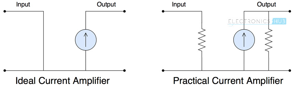
Notice the resistances at the input and output of a current amplifier in real life scenario. The resistance in series to the input indicates the effective impedance created by the amplifying circuitry. The resistance parallel to the output denotes some of the output signal lost either by feedback mechanisms or because of internal losses.
Current Amplifier Circuit Diagram
Below is the circuit diagram of a simple 2-stage current amplifier circuit that uses npn and pnp transistors as the amplifying element.
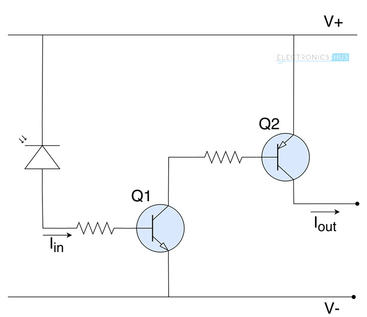
The photodiode absorbs energy from light and releases electrons, thereby acting as an input current source. This current from the photodiode is first amplified by the transistor Q1 and is further amplified by the transistor Q2.
The resistors at the bases of both the transistors are used to adjust the gain. The number of times a signal is amplified is same as stages in an amplifier. Here the current is amplified twice, so this is a 2-stage current amplifier.
Coming to the calculation part, let’s say id is the current flowing from the photodiode and Ai1 , Ai2 are the gains of transistors Q1 and Q2 respectively.
The current at the output of first transistor will be equal to Ai1id, and this will be the input to second transistor. The second transistor Q2 will further amplify this signal by a factor of Ai2.
So, the final output current will be equal to Ai2Ai1id , effectively making gain of this entire two stage current amplifier equal to Ai2Ai1.
Applications of Current Amplifiers
Following are some of the practical applications of current amplifiers:
- In amplifier systems, current amplifiers are used to obtain a better bass output, by increasing the intensity with which the speakers are driven.
- Current amplifiers with variable gain are used in many industrial manufacturing systems like laser and water jet cutting machines to control the intensity with which the fabrication is done
- In sensor systems, current amplifiers are used to strengthen weak input signals, for use in subsequent circuits
Current Buffer
Introduction
Current buffer is an electronic circuit that is used to transfer electric current from input source having very less impedance (effective resistance) to output loads with high impedance. It is designed to prevent signal sources from getting affected because of any differences in the amount of current drawn by output loads.
In most scenarios it acts as a bridge between weak input signals (like signals from sensors) and output loads that might draw larger currents. Below is the diagram of an ideal current buffer.
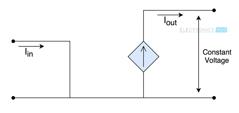
It is primarily designed to remove the influence of output load on the input source. So you can think of current buffer as a circuit that isolates input and output circuitries while allowing the required flow of current to the output load in order to maintain a constant voltage across it.
Practical Use of a Current Buffer
Consider a circuit that uses an LDR sensor to drive a robot. The current consumed by the motors of robot is not constant and depends on the surface inclination or roughness i.e. load on the motors.
So, if the motors are directly coupled with the temperature sensor using a current amplifier or other similar drivers, the motors might sometimes draw more current which affects the accuracy of the sensor. The voltage across the motors will change as well, which in turn changes speed of the robot.
In order to prevent that from happening, current buffers are used. They can provide desired current to the motors without affecting accuracy of the sensor, while maintaining a constant voltage across the terminals of motors i.e. output loads.
Current Follower
A current buffer circuit with a Gain of 1 (i.e. the input and output currents are the same) is named as a current follower. It means that a current follower circuit does not provide any amplification of current to the input signal.
You might be wondering why a current follower circuit is used as the input and output currents from the current follower are the same. The reason is that a current follower not used to increase the output current.
But it is used to isolate input and output terminals while allowing the same amount of current flow into the input, and from the output. This is the reason why current follower circuits are also called as isolation buffers.
Current Buffer Circuit Diagram
Below is the circuit diagram of a simple mosfet current buffer.
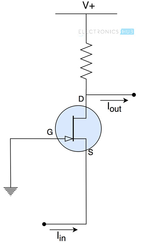
This arrangement provides very less impedance to the input signal and high impedance at the output terminal, making it a near ideal current buffer.
Applications of Current Buffers
Following are some of the practical applications of current buffers:
- In digital logic gates, current buffers are used to isolate input signals from the succeeding circuits
- Current buffers are used in high precise sensor systems in order to reduce the influence of voltage/current fluctuations because of varying output impedances
- In motor drivers and other electrical actuator systems
Current Amplifiers vs Current Buffers
At first glance, current amplifiers and current buffers may seem similar. Both take in a weak signal and produce a stronger signal (in terms of current) at the output. But the main differences lie in the manner input signal is amplified.
For current amplifiers, the magnitude of current at the output terminals is always a fixed multiple of the magnitude of input current. So given the magnitude of current of the input signal, we can easily calculate the current at the output by multiplying the input current with gain of the amplifier.
This is not the case for current buffers. The difference is that current buffers are designed to provide as much current as the load demands, while maintaining a constant voltage across it. So unless we know how much current the output load demands, we can’t determine by what factor a current amplifier amplifies the input signal.
Simply put, the gain in current of a current buffer is not constant and varies depending on current demanded by the output load, while the gain of a current amplifier is constant irrespective of the output device.

2 Responses
Very good and informative information. I have a question . can i amplify the current of any step down transformer for load. For example a load require 800ma but the transformer give only 500ma current . Then Is it possible to increase the current from transformer in this case ?
Thank you. Very informative post. Can I get a help from here? I have source pulse type voltage of irregular magnitude ( order 150-200 Volt) and it provides 0.1 micro Amp through 1 Mega-ohm load. Can I increase the value of current 100 times through this above circuit? If yes, can you suggest the value of resistances for the circuit designing and also suggest if there any other way with transistor.
Thanks again.