A Differential Amplifier Circuit with Transistors boosts the difference between two signals but ignores signals that are the same on both. It usually has two transistors sharing one connection and takes two inputs. This circuit is crucial for improving signals, cutting down noise, and focusing on the difference between signals. It’s a basic part of operational amplifiers and is widely used in processing signals and measuring things.
Differential Amplifier Circuit Using Transistors
The amplifier which amplifies the difference between two input signals is called as Differential amplifier. The differential amplifier configuration is very much popular and it is used in variety of analog circuits. It is basic building in operational amplifiers. Below figure shows the ideal differential amplifier.
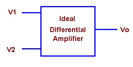
Here V1 and V2 are the two input signals of the Differential amplifier and Vo is the single ended output of Differential amplifier. In an ideal differential amplifier the output voltage Vo is proportional to the difference between two input voltages.
Vo ∝ (V1 – V2)
Vo = Ad (V1 – V2)
Differential Gain Ad:
Differential gain is the gain with which amplifier amplifies the difference between two input signals. It is denoted as Ad.
Vo = Ad (Vd)
Where Vdis the voltage difference between two input signals i.e. Vd= V1 – V2
Ad= Vo / Vd
Differential gain in dB is given as
Ad(dB)= 20 log10 (Vo / Vd)
Common Mode Gain Ac:
If we apply two input voltages which are equal to the differential amplifier then ideally output voltage must be zero. But it is not the case in practical amplifier because output of differential amplifier not only depends on the difference but also depends on the average level of the 2 inputs. Average level of the 2 input signals is called as common mode signal denoted as Vc.
Vc = (V1 + V2) / 2
The gain with which differential amplifier amplifies the common mode signal is called as common mode gain.
Ac = Vo / Vc
So the total output of any differential amplifier is given as
Vo = Ad Vd + AcVc
CMRR (Common Mode Rejection Ratio):
In common mode configuration of differential amplifier many noise signals appear as common input to the both terminals of amplifier. So it better to reject such a common signal.
CMRR is defined as the ability of differential to reject the common mode signal. In other words it is defined as the ratio of differential mode voltage gain Ad to the common mode gain Ac.
CMRR = ρ = Ad / Ac
Vo = AdVd[1 + (1/CMRR)(Vc/Vd]
The above formula is used to calculate the output voltage of differential amplifier.
Features of Differential Amplifier:
- Differential voltage gain is high
- Common mode gain is low
- CMRR (common mode rejection ratio) is high
- Input impedance is high
- Wide bandwidth
- Low offset voltages and currents
- Output impedance is low
Transistorized Differential Amplifier:
Differential amplifier basically uses emitter biased circuits which are identical in characteristics. This differential amplifier is also called emitter coupled differential amplifier. The below figure shows the circuit diagram of differential amplifier.
Differential Amplifier Circuit:
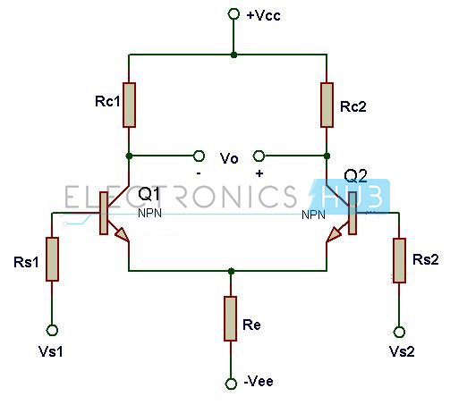
Input1 of differential amplifier is connected to the base of transistor Q1 and input2 of the differential is connected to the base of another transistor. VCC and VEE are the two supplies for differential amplifier. The circuits works proper even with a single supply voltage. If you want to run the differential amplifier with a single supply then connect VCC to supply voltage and VEE to ground.
Working of Differential Amplifier:
If input signal is applied to the base of transistor Q1 then there is voltage drop across collector resistor Rc1 so the output of the transistor Q1 is low. When there is no input voltage to the transistor Q1, the voltage drop across resistor Rc1 is very less as a result output transistor Q1 is high.
When transistor Q1 is turned on, the current through the emitter resistor Re increases as emitter current Ie is almost equal to the collector current Ic. As a result voltage drop across resistor Re increases and makes emitter of both transistors positive. In this condition transistor Q2 does not conducts as there is no base voltage. As a result collector voltage of transistor Q2 is high. Hence it is clear that the output is produced at the collector of transistor Q2 when an input is applied to the base of Q1.
Transistors Q1 and Q2 have the exactly same characteristics. The two collector resistors are equal while the 2rwo emitter resistances Re1 and Re2 are also equal.
Rc1 = Rc2 and Re1 = Re2.
The magnitudes of supply voltages +Vcc and -Vee also same. If the input voltages Vs1 and Vs2 are equal then emitter currents Ie1 and Ie2 are also equal.
If Vs1 = Vs2 then Ie1 = Ie2.
Total emitter current is given as
Ie = Ie1 + Ie2
Ve = Vb – Vbe.
Vc1 = Vc2 = Vcc – IcRc assuming collector resistances Rc1 = Rc2 =Rc.
Differential Amplifier Applications:
- Differential amplifier is used as voltage comparator.
- It is used in voltage subtractors.
- Used in operational amplifiers to amplify the input signal.
- Differential amplifier is used as a voltage follower.

One Response
i need more facts about this project please