A Calculator is a device that is used to perform simple arithmetic operations to complex mathematical calculations. The rise of calculators can be seen from devices like Abacus to credit card sized complex electronic solid state devices in the modern day usage.
Apart from small calculators, which can be used to perform simple arithmetic calculations, calculators also come in complex scientific outlook that can perform various mathematical and statistical operations like trigonometry, algebra, calculus, etc. But such complex scientific calculators can be very costly.
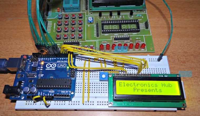
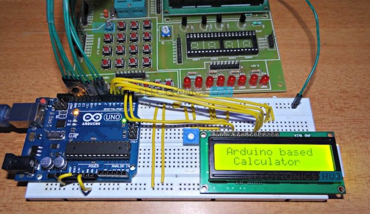
In this project, we will design a simple arithmetic calculator using Arduino UNO, a 16 x 2 LCD display and 4 x 4 Matrix Keypad.
How to Build a Simple Arduino Calculator?
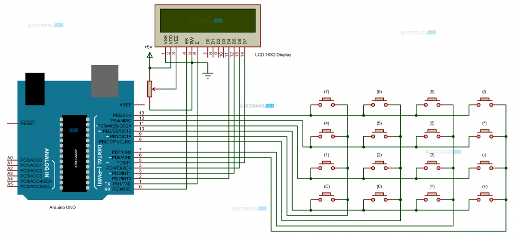
Circuit Diagram
Components
- Arduino UNO [Buy Here]
- 16 x 2 LCD Display [Buy Here]
- 4 x 4 Matrix Keypad Module or 16 Push buttons
- 10 KΩ Potentiometer
- Bread board ( Prototyping board )
- Connecting wires
Component Description
Arduino UNO:
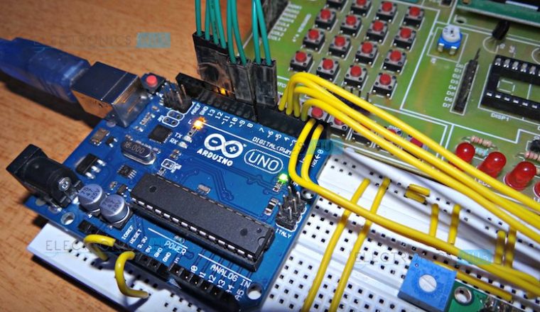
The Microcontroller part of the project is the Arduino UNO. It controls the LCD and matrix keypad and also performs the necessary calculations as per the user input.
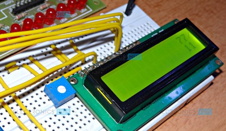
16 x 2 LCD Display:
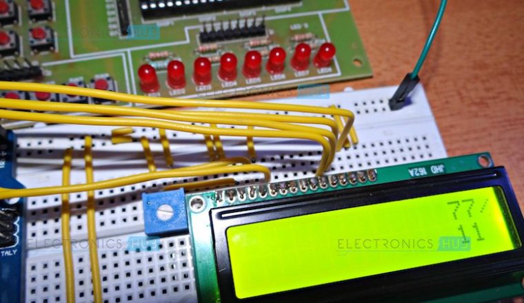
It is a simple alpha – numeric display module that is used to display the welcome messages, user inputs and finally the output of the calculations.
4 x 4 Matrix Keypad:
Keypads are a part of Human Machine Interface and play really important role in embedded systems where human input is needed. Matrix Keypads are commonly used in calculators, telephones etc. where a number of input switches are required.
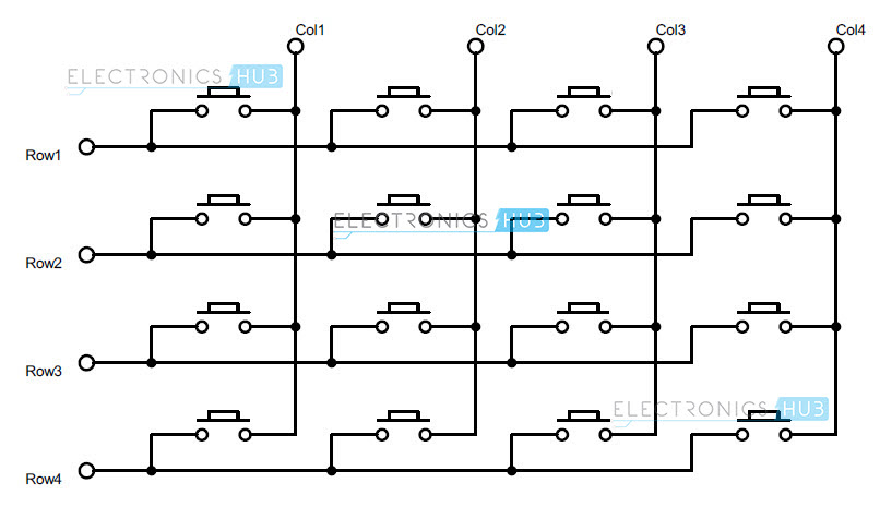
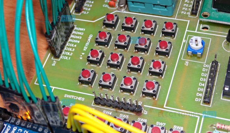
Construction of a 4X4 keypad is really simple. It consists of 16 buttons or switches arranged in the form of an array containing four rows and four columns. One end of the pushbutton is connected to one row, and the other end is connected to one column.
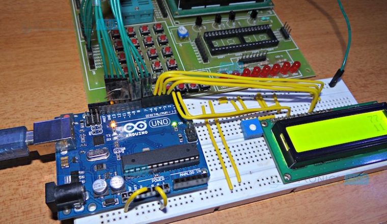
Circuit Design
The design of the circuit is simple to understand but a little bit messy to implement as it involves a lot of connections and wires. The design of the circuit is explained here.
First, the connection of LCD display to Arduino UNO. LCD is used in 4 – bit mode and hence, only 4 data connections are needed. The data pins D4 through D7 (Pins 11 – 14) are connected to digital I/O pins 2 through 5 of the Arduino.
Then, we need to connect the three control pins of LCD i.e. RS, RW and E. RS (Pin 4) is connected to Pin 0 of the Arduino. E (Pin 6) is connected to Pin 1 of the Arduino. RW (Pin 5) is connected to ground.
Note:
RS and E are connected to Pins 0 and 1 of Arduino which are usually associated with serial communication. We must be careful while programming the device and hence we must disconnect these two connections while we are programming Arduino UNO.
The next connections are with respect to power supply of LCD. Pin 1 (VSS) is connected to ground and Pin 2 (VDD) is connected to 5V supply. Pin 3 (VEE) is connected to a POT for adjusting the contrast of display.
Pin 15 and Pin 16 are supply pins for backlight LED. They must be connected to 5V and ground supply.
The next connection is with respect to matrix keypad. The 4 row pins of the keypad (row 1 to row 4) are connected to pins 13 through 10 of Arduino UNO and the 4 column pins (col 1 to col 4) are connected to pins 9 through 6 of Arduino UNO.
Working Process
A simple calculator is designed in this project using Arduino UNO board and a keypad matrix. The working of the project is explained here.
The keypad in the project consists of 4 rows and 4 columns and the structure is similar to the image shown below.
A special library called “Keypad.h” is used in order to find out which key is pressed. This library must be downloaded separately and must be added to Arduino IDE.
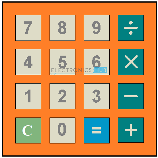
When the key is determined, relevant operations like addition, subtraction, multiplication and division can be performed. A clear screen (of LCD display) button is also included.
Even though the library does the most of the work, we can understand the processing of determining the key.
As mentioned in the circuit design, the rows of the keypad are connected to pins 13 – 10 of Arduino and columns of keypad are connected to pins 9 – 6 of Arduino.
All the row pins are pulled high and all the column pins are pulled low. From now onwards, the Arduino waits for the column pin to become HIGH, which happens if a key is pressed.
Consider, if a key is pressed, the switch closes the connection between the corresponding row and column. Due to the flow of current from high to low potential, the column will become high.
This change in potential at the column, makes the Arduino to understand that the key corresponding to the particular column is pressed.
Now it’s time to find the row. Instead of giving HIGH signal to all the rows at once, Arduino will enable HIGH to one row at a time and check whether there is a HIGH signal detected on the column. If there is no HIGH signal detected on the corresponding column, Arduino will scan for the next row.
This process will repeat until there is a HIGH signal detected on the corresponding column. Once if the HIGH signal is detected on the corresponding column, thus the row is identified.
From the outside, this key detection process seems to be taking long time but really the time taken to complete all the above mentioned process will be in micro seconds. But the average time a human takes for pushing a button is in milli seconds. That’s why, the key detection process will start when the key is pressed and completes before the key is released.
Advantages
- A simple arithmetic calculator is implemented in this project using Arduino UNO, matrix keypad and LCD.
- Can be extended to perform complex calculations, but the logic must be carefully designed in order to solve those calculations. This may even result in increased number of switches.

12 Responses
It is clearly understanding method what your given. I will keep on watching.
I need the full project write up, on how to build a simple arduino calculator
Hi, thnx so far for an understable code ^_^
However, I need help with following:
– calculating with parenthesis
– trigonometry
– square root
– faculty
All these with an LCD-display and 4×4-keypad like you did.
Hi, It is difficult to implement such complex calculator with just 4×4 matrix keypad. We will try and update it soon.
Can I do the program without lcd?
I only have I2C
I had all the wiring correctly done, but in the code, there was an error message saying:
Arduino: 1.8.5 (Windows Store 1.8.10.0) (Windows 10), Board: “Arduino/Genuino Uno”
C:\Users\Syed Mohsin Hasan\Documents\Arduino\Calculator2\Calculator2.ino: In function ‘void loop()’:
Calculator2:53: error: ‘num1’ was not declared in this scope
num1 = num1 + key;
^
Calculator2:60: error: ‘num2’ was not declared in this scope
num2 = num2 + key;
^
Calculator2:82: error: ‘num1’ was not declared in this scope
answer = num1.toInt() + num2.toInt();
^
Calculator2:82: error: ‘num2’ was not declared in this scope
answer = num1.toInt() + num2.toInt();
^
Calculator2:85: error: ‘num1’ was not declared in this scope
answer = num1.toInt() – num2.toInt();
^
Calculator2:85: error: ‘num2’ was not declared in this scope
answer = num1.toInt() – num2.toInt();
^
Calculator2:88: error: ‘num1’ was not declared in this scope
answer = num1.toInt() * num2.toInt();
^
Calculator2:88: error: ‘num2’ was not declared in this scope
answer = num1.toInt() * num2.toInt();
^
Calculator2:91: error: ‘num1’ was not declared in this scope
answer = num1.toInt() / num2.toInt();
^
Calculator2:91: error: ‘num2’ was not declared in this scope
answer = num1.toInt() / num2.toInt();
^
Calculator2:103: error: ‘num1’ was not declared in this scope
num1 = “”;
^
Calculator2:104: error: ‘num2’ was not declared in this scope
num2 = “”;
^
exit status 1
‘num1’ was not declared in this scope
This report would have more information with
“Show verbose output during compilation”
option enabled in File -> Preferences.
Hi! I was wondering, are the cables soldered to the LCD?
If they are, do you think there’s some other possible way to connect the cables to the LCD without soldering them? Would it work if I used a LCD KeyPad Shield?
Thank you! 🙂
No. They are not soldered. We just connected them to the breadboard. You can use LCD Keypad shield. Just insert the correct pin numbers in the code.
Thank you!!
It is not working only lcd is glowing , i made same circuit as yours can you identify my mistake
Where is the decimal pojnt ?
It’s only for integers ?
Regards !
Does anyone have the shopping list for all of this?