In this tutorial, we will learn about 4×4 Matrix Keypad and how the Arduino Keypad Interface works. A Keypad is an input device that is used to enter passwords, dial a number, browse through menu and even to control robots.
You might have seen keypad being used at ATMs, Security Systems, Telephones etc. where the users are allowed to input data to the system. Keypads can be used with Microcontrollers and prototyping platforms like Arduino to implement a variety of projects.
So, in this article, I’ll show you how to interface a 4×4 Matrix Keypad with Arduino and how to acquire the data from the keypad.
Overview
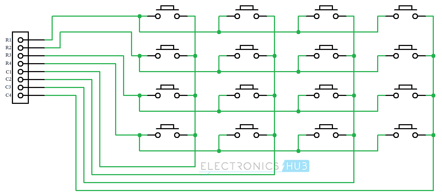
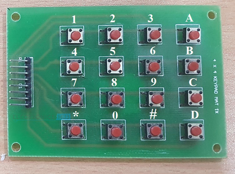
A matrix keypad is nothing but a systematic arrangement of buttons in horizontal and vertical fashion. For example, a 4×4 Keypad consists of 16 keys or buttons that are arranged in 4 Rows and 4 Columns. The following image shows a typical Button Type 4×4 Matrix Keypad.
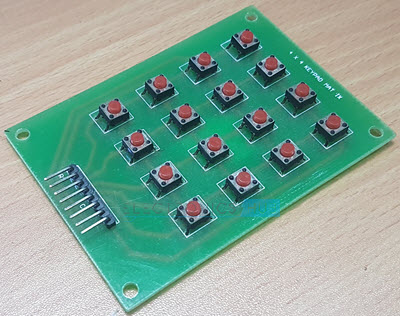
There are two types of matrix keypads available today. One is the traditional Button type Keypad as shown in the image above while the other is a Membrane type Keypad, which doesn’t contain any buttons but works due to electrical contact between surface of the key and the underlying circuit.
Also read: How to Build a Simple Arduino Calculator?
How Keypads Work?
As mentioned earlier, a 4×4 Matrix Keypad consists of 16 Keys or Buttons arranged in four rows and four columns. The internal circuit of the 4×4 Keypad with all the 16 buttons is shown in the following image.
I’ll explain the working of the 4×4 Matrix Keypad in general without considering any specific microcontroller. This working can be applied to any Microcontroller, even Arduino and Raspberry Pi.
Assume all the rows of the Keypad are made LOW and all the columns of the Keypad are made HIGH by the Microcontroller. When no button or key is pressed, this will be the default status of the rows and columns.
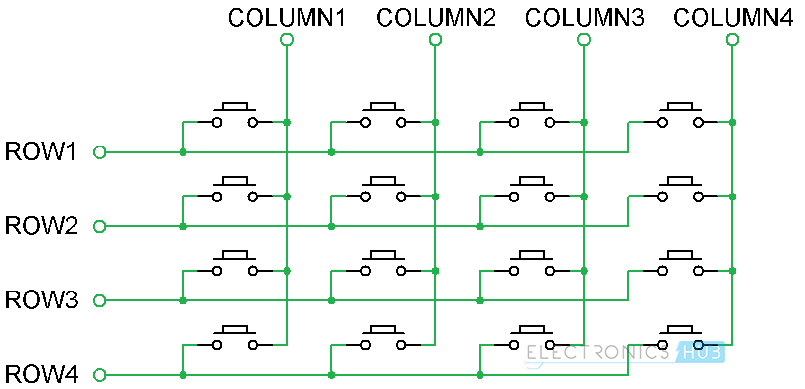
Now, when a key is pressed, the corresponding column will become LOW as the current flows from HIGH Column Pin to LOW Row Pin. The Microcontroller (or Arduino) can easily identify the Column of the Key just by scanning for LOW on Columns.
The trick part comes in identifying the Row of the Key. For this, the Microcontroller should make the Rows of the keypad HIGH, one-by-one and check for the Column Pins to become HIGH. This procedure is continued till the earlier detected Column becomes HIGH.
This way, the microcontroller can determine both the Column and the Row of the Key and hence the Key pressed is identified.
Arduino Keypad Interface
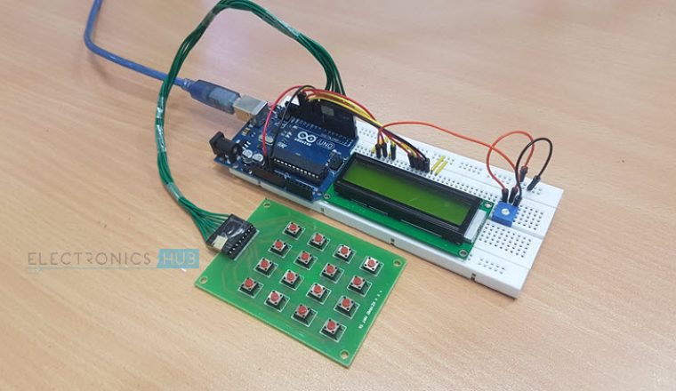
Now, I’ll show you how to interface or connect the 4×4 Keypad with Arduino UNO. A 4×4 Matrix Keypad consists of 8 pins and we need to use 8 pins of Arduino to connect to the keypad. The following image shows the simple circuit of the Arduino Keypad Interface.
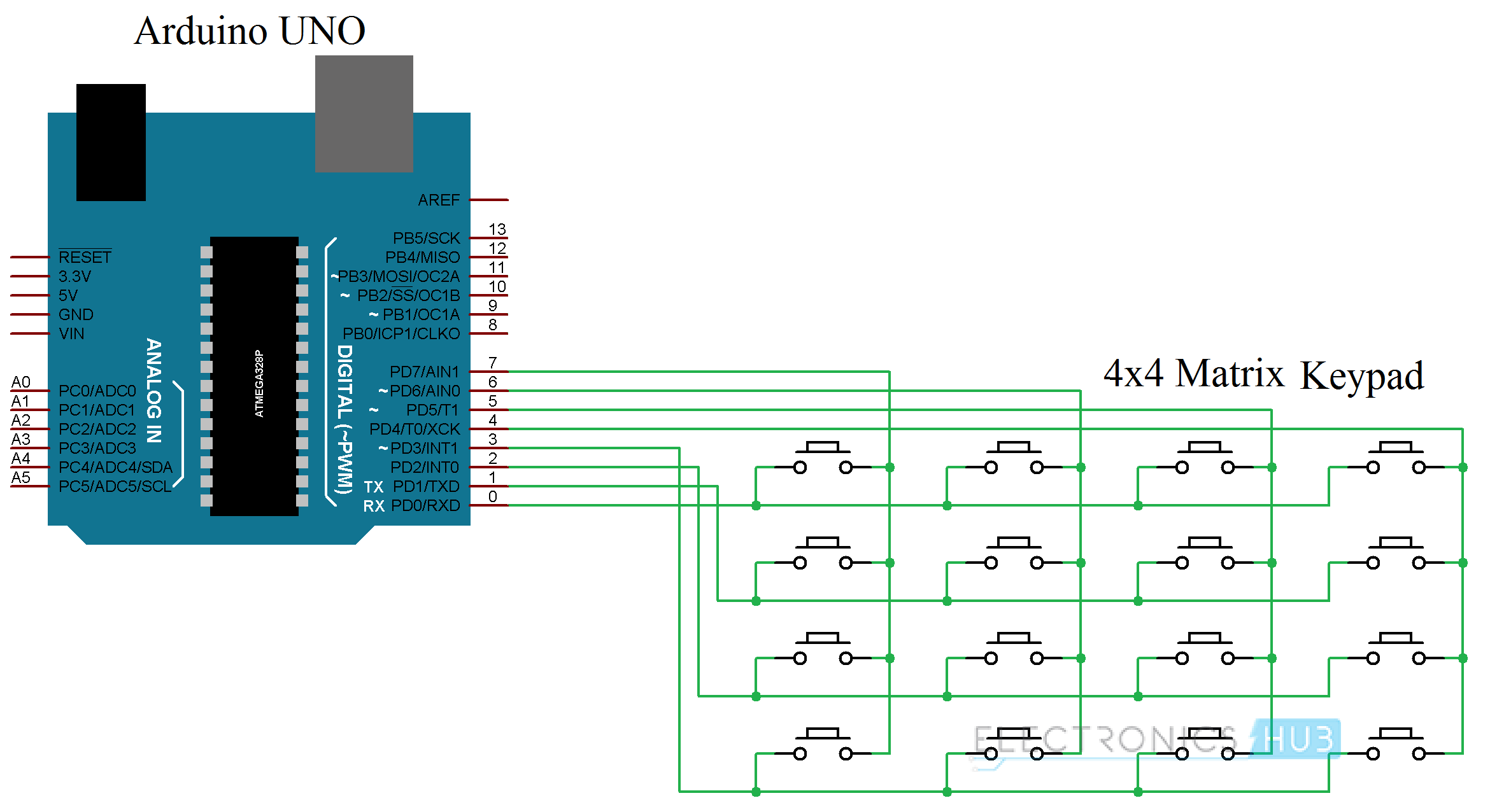
In this circuit, I’ve connected the Rows of the keypad to the Digital Pins 0 through 3 of the Arduino i.e. ROW1 to Digital Pin 0, ROW2 to Digital Pin 1, ROW3 to Digital Pin 2 and ROW4 to Digital Pin 3.
Similarly, the Columns of the Keypad are connected to Digital Pins 4 through 7 of Arduino. We will now see a small project using Arduino Keypad Interface.
Circuit Diagram
Components Required
- Arduino UNO
- 16×2 LCD Display
- 4×4 Matrix Keypad
- 10KΩ Potentiometer
- 1KΩ Resistor (1/4 Watt)
- Breadboard
- Connecting Wires
- Power Supply
Circuit Design
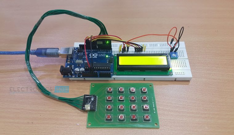
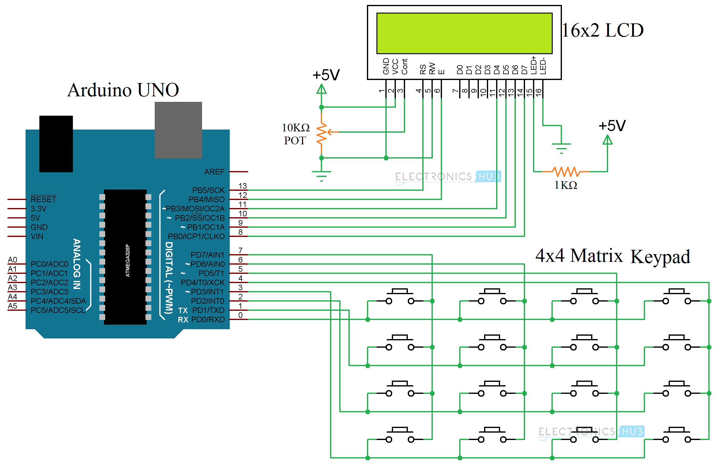
The circuit design of the project is very similar to the Arduino Keypad interface shown above. The additional component is the 16×2 LCD Display. The data pins of the LCD are connected to Digital Pins 11 through 8. The E and RS Pins of the 16×2 LCD Display are connected to Pins 12 and 13 of Arduino.
Code
Working
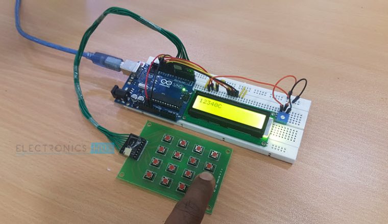
The aim of this simple project is to explain how to interface a 4×4 Matrix Keypad to Arduino, how the Arduino Keypad Interface works and how to determine the key pressed on the keypad and display it on the 16×2 LCD Display.
In order to determine the Key pressed on the Keypad, we have use a special library called, well “Keypad”. You should first download this library and place it in Arduino/libraries directory (C:\Program Files (x86)\Arduino\libraries or C:\Program Files\Arduino\libraries).
NOTE: The library “Keypad” was developed by Mark Stanley and Alexander Brevig.
After installing the library, you can copy the above code and upload it to Arduino. In the code, the keys of the 4×4 Matrix keypad are mapped with digits from 0 to 9, symbols * and # and alphabets A, B, C and D.
So, whenever a key is pressed, Arduino will detect the key using the “Keypad” library and display the same on the 16×2 LCD Display.
Applications
There are a wide range of application of the Arduino Keypad Interface. Some of them are mentioned below.
- Arduino based Calculator
- Password based Door Lock System
- Home Security Systems
- Home Automation Systems

3 Responses
Thank you for the tutorial. I have a followup question:
I have an UNO R3 Arduino kit.
I am wanting to use the 4×4 keypad,to control some LED lights. But I am already using Pin 7 to control the LED lights..
How can I use the 4×4 keypad at the same time?
Thank you,
You can use any Digital I/O Pins of the Arduino to connect the Keypad. All you need is 8 pins (which can be any 8, not in any specific order). Just be careful in assigning the rows and columns in the code.
Thanks for your tutorial, it’s very helpful, but I want to use it with STM32 blue pill, the keypad doesn’t work correctly, I added resistors to pullup the columns, the keypad works but not perfectly, please if you can help me I appreciated.