In this project, we will see how to make an RGB LED Matrix using simple components. LED Matrix is one of the popular Arduino projects among several DIY and hobby projects. An RGB LED Matrix is one such project which many students and hobbyists put it on their to-do list of Arduino Projects.
An LED Matrix can be used in sign boards with scrolling messages, display animations, synchronized music spectrum, etc.
It is really fun to build an RGB LED Matrix as it involves different aspects like circuit design, constructing the matrix, assembling the components and coding.
In this tutorial, we will show you how to make you own 8×6 RGB LED Matrix using Arduino Nano, HC-06 Bluetooth Module and an Android Phone with custom app. So, let us get started with building your own RGB LED Matrix.
NOTE: This tutorial is based on the work of Alexandar AS5.
Also read this SIMPLE ARDUINO 8X8 LED MATRIX
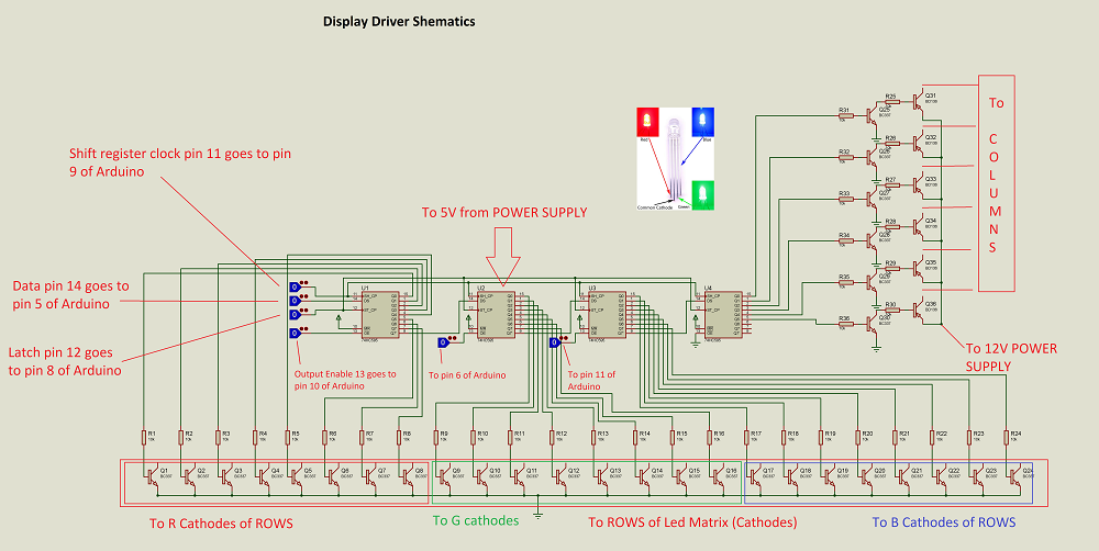
Circuit Diagram
This is circuit of RGB LED Matrix project. The first image shows the connections with respect to the shift registers, how the shift registers are connected to Arduino Nano, source transistors connected to the Columns (assuming Common Anode RGB LEDs) and sinking transistors connected to the Rows of R, G and B LEDs (Cathodes).
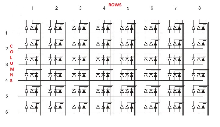
The second image here shows the layout of the RGB LEDs. They are organized into 8 rows of Cathode terminals and 6 columns of anode terminals. Each row is further consists of 3 cathode terminals for Red, Green and Blue LEDs.
Components Required
- Arduino Nano
- Bluetooth module HC-06
- 48 X Common Anode RGB LEDs
- 6 X BD136 power PNP Transistors
- 30 X BC337 NPN Transistors
- 4 X 74HC595N Shift Register IC
- 36 X 10KΩ Resistors (¼ W)
- LM35 Temperature Sensor
- Power supply
- A lot of wires and materials like plywood and polystyrene sheet
Component Description
Arduino Nano
Arduino nano is an ATmega Microcontroller based prototyping board. It has 14 digital I/O and 8 analog pins of which 6 digital pins are used for this project and 1 analog pin is used for temperature reading.
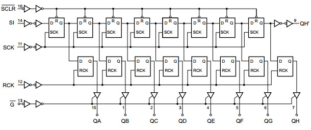
74HC595N
74HC595N is 8-bit serial-in, serial or parallel-out shift register with output latches. In this project it’s used 4 this ICs which acts like one 32-bit-shift register. Function of this IC is to convert serial to parallel communication for getting more digital output pins, outputs are connected to transistors to drive RGB LEDs.
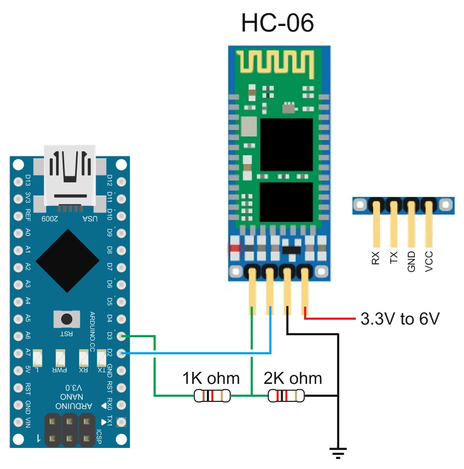
Bluetooth Module HC-06
This module is great for interesting projects controlled by android and it’s really easy to use.
It’s based on serial communication with Arduino, but with logic of 3.3V, so it’s recommended to add two resistors, which acts like voltage divider, to adapt voltage levels.
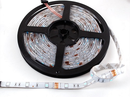
LED Strip
For this project, we have used an RGB LED strip, like the one shown below with 30 LEDs per meter. It is necessary to cut the LED strip into pieces, where every piece has 3 RGB LEDs and acts like one pixel. By using LED strip, you will get really good brightness of the screen.
How to Build the RGB LED Matrix?
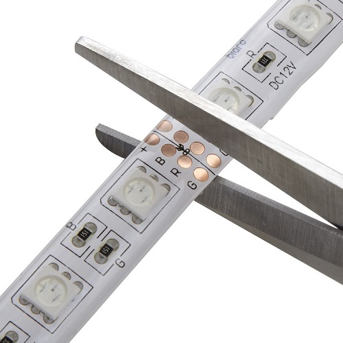
Let us now take a step-by-step look into how to build the RGB LED Matrix. First, we will start with the RGB LED Strip. You should cut the LED strip consisting of 3 LEDs, Red, Green and Blue respectively, as shown below.
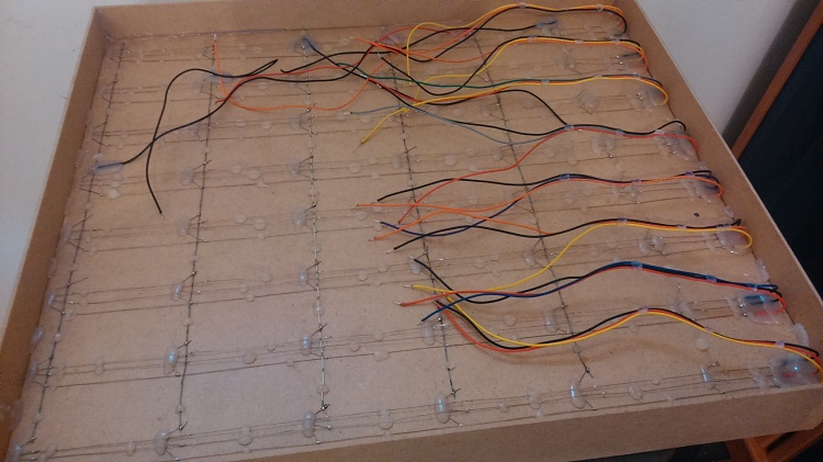
Then peel off the protective tape and paste each pixel (consisting of 3 LEDs on the LED strip) to panel and drill small holes through R, G, B and V+ metal contacts.
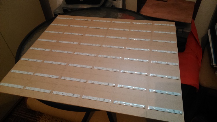
Solder contacts and implement short wires to the other side of the board and use hot glue to make it on place. Then connect all rows and columns together.
Separate each pixel with bulkheads made of same material but colored in white to reflect light.
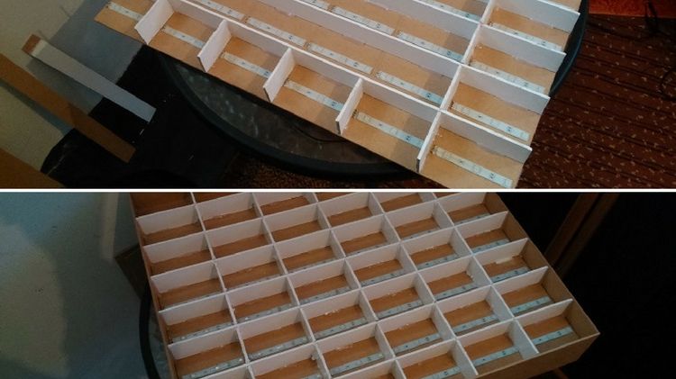
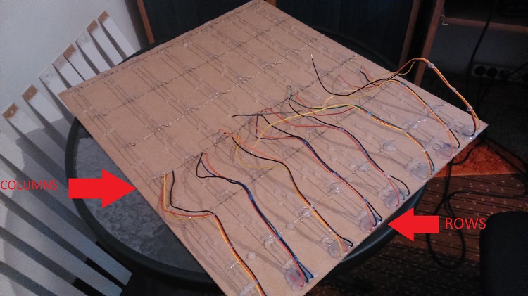
Now on the other side there are all contacts of rows and columns as show below.
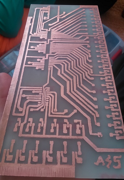
Print the circuit on a paper, transfer it on a PCB and drill small holes on marked places.
Place the components on PCB as shown below.
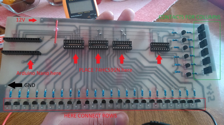
NOTE: Arduino Nano has +5V auto selector, so don’t care about burning your controller.
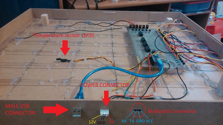
Final inside appearance is shown below. Note the connectors for power supply, Bluetooth and USB are placed on the top of the panel for easy access.
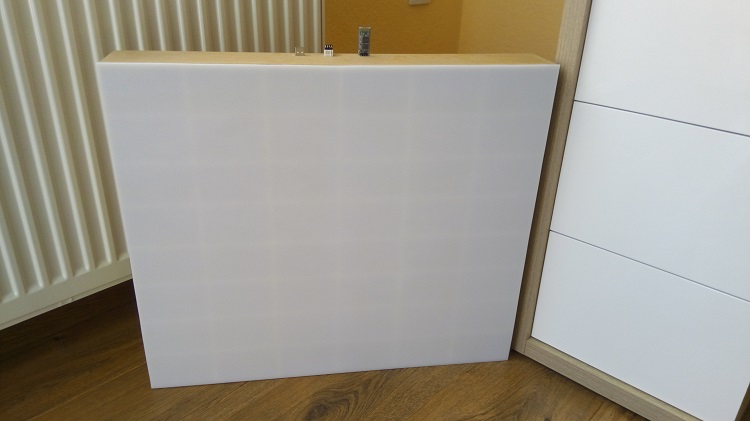
And finally coming to the front of the matrix, put the polystyrene sheet on the surface of the screen. The finished RGB LED Matrix looks something like this.
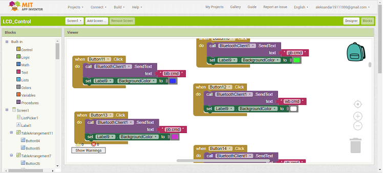
Create an APP for Android using MIT App Inventor 2
In order to control the RGB LED Matrix through an Android Phone, we need to create a dedicated App. For this, we will be using the MIT App Inventor 2, an open source, web based application for developing Apps for Android devices.

One Response
Where did you buy the LED strip from? Can you suggest the brands of strips one can use?