In this project, we will learn about 7 Segment Displays and see how the Arduino 7 Segment Display Interface works. 7 Segment Display or Seven Segment Display is one of the simplest display devices that can be connected to Arduino or any microcontroller.
There are several display devices like alphanumeric LCD, graphical LCD, touchscreen etc. a simple 7 segment display is sufficient for many applications.
Devices like washing machines, microwave ovens, etc. still use 7 segment displays for displaying information like quantity and time. The main reason for this is their simple interface and low cost.
If your project involves displaying just numbers, then a 7 Segment Display is your safe bet instead of the expensive 16×2 LCD Display.
A brief Introduction to 7 Segment Display
A 7 Segment Display is a simple device. It consists of 7 LEDs called arranged in Segments. Hence, the name 7 Segment Display. Each LED Segment is in the shape of hexagon and all the 7 LEDs are arranged in an “8” like fashion so that it can display digits from 0 to 9.
We have already seen how to interface a 4-Digit 7 Segment Display to Arduino in an earlier tutorial. If you recall that project, I’ve mentioned that seven segment displays are of two types: Common Anode and Common Cathode.
For the purpose of this project, I’ll be talking about Common Anode 7 Segment Display. Before going further, let us first take a look at the internal structure of a Common Anode 7 Segment Display i.e. how the LEDs are connected.
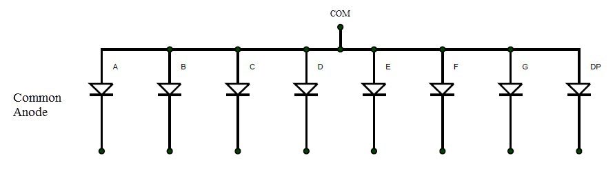
You can observe that all the anodes of the individual LEDs are connected together and all the cathodes are left open. In order to turn on a segment, the common terminal is connected to +ve (positive) of the supply and whichever cathode is connected to the –ve (negative) of the supply that particular segment will light up.
NOTE: In case of Common Cathode 7 Segment Display, the common terminal will be Cathode, which must be connected to GND.
Now, let us see the pin diagram of a Common Anode type 7 Segment Display. The following image shows a simple common anode seven segment display. It consists of 10 Pins.
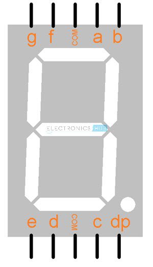
The top five pins are ‘g’, ‘f’, ‘COM’, ‘a’ and ‘b’ while the bottom five pins are ‘e’, ‘d’, ‘COM’, ‘c’ and ‘dp’. Since it is a common anode display, the COM (common pin) is connected to the VCC.
NOTE: In case of a common cathode 7 segment display, the pin configuration will be the same but the COM pin must be connected to GND.
In order to display digits from 0 to 9 on this 7 segment display, you need to activate certain segments for each digit. The following table indicates the list of segments you need to turn on in order to display a particular digit.
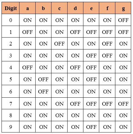
The above table can be useful while programming Arduino or any other microcontroller.
Now that we have seen a little introduction about 7 Segment Display, let us see how to interface a common anode 7 segment display to an Arduino.
Arduino 7 Segment Display Interface
Project 1: Simple Arduino 7 Segment Display Interface
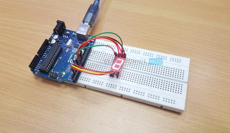
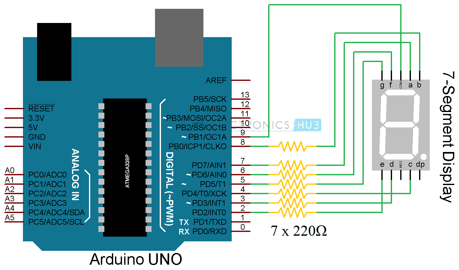
In the first circuit, I’ll show you how to connect a common anode 7 segment display to Arduino UNO and display digits from 0 to 9 in a loop. The circuit diagram, components, code and working of this circuit are explained here.
Circuit Diagram
Components Required
- Arduino UNO
- 7 Segment Display
- 7 x 220Ω Resistors (1/4 Watt)
- Breadboard
- Power Supply
- Connecting Wires
NOTE: In the practical implementation, I haven’t connected the current limiting resistors to the individual LEDs of the 7 Segment Display. But I recommend you to connect those resistors.
Code
Working
This is a simple project which explains the working of the Arduino 7 Segment Interface. The 7 segment pins of the display are connected to Arduino as follows
- a – Arduino Pin 7
- b – Arduino Pin 8
- c – Arduino Pin 4
- d – Arduino Pin 3
- e – Arduino Pin 2
- f – Arduino Pin 6
- g – Arduino Pin 5
Since the 7 Segment Display used in this project is of type common anode one, the common pin is connected to Pin 9 of Arduino and is always made HIGH.
In order to turn on a particular segment, segment ‘a’ for example, the corresponding Arduino Pin must be made LOW. Here, the segment ‘a’ is connected to pin 7 of Arduino. Similarly, other segments can be made LOW and according to the above table, depending on the segments selected, a digit will be displayed on the 7 Segment Display.
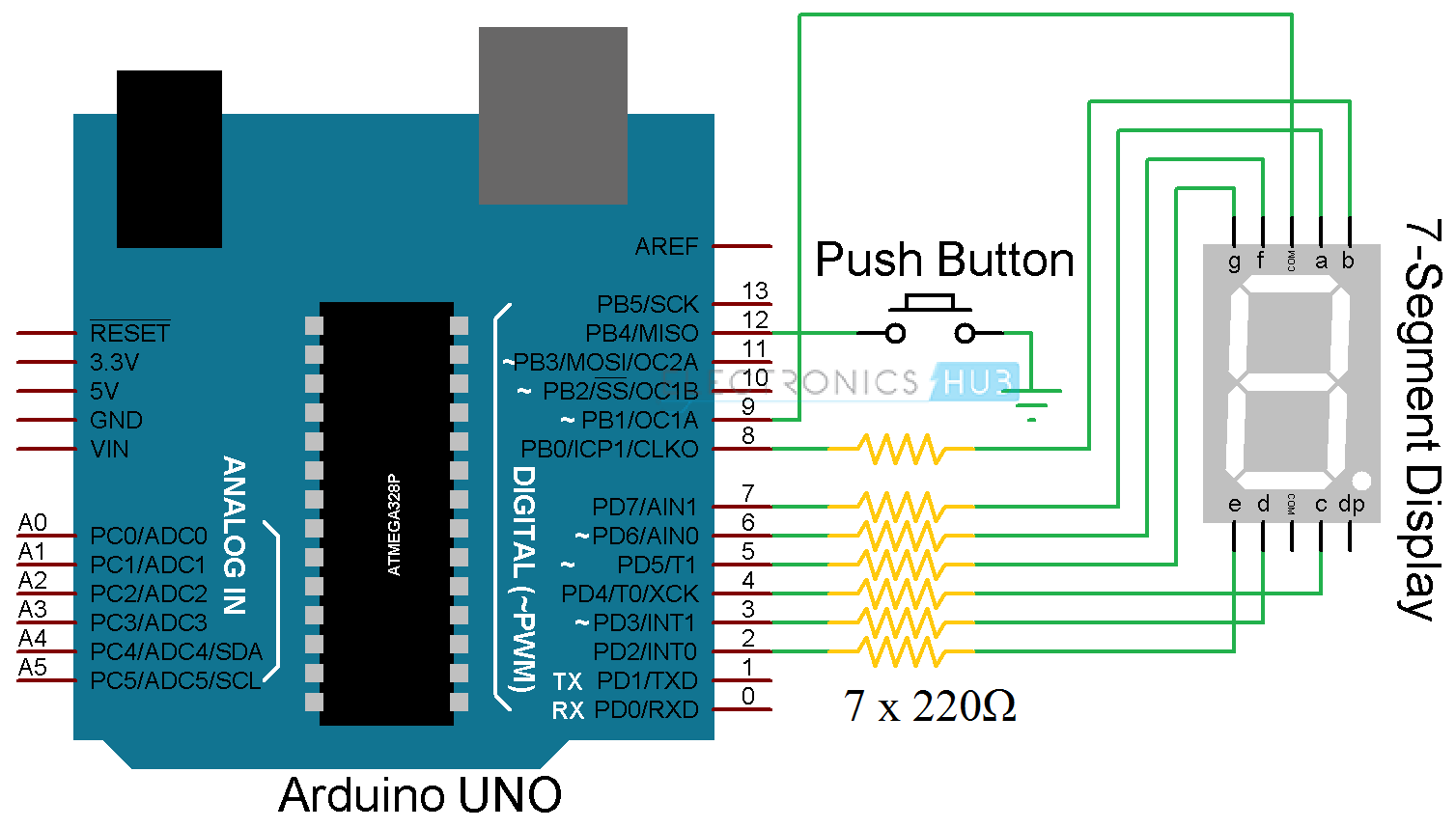
Project 2: Rolling Dice using Arduino and 7 Segment Display
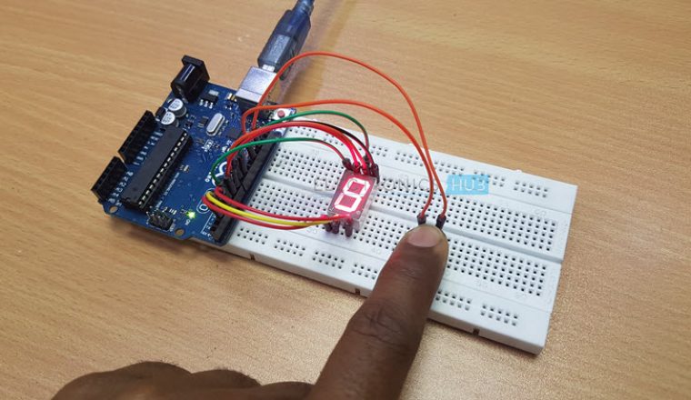
In the second circuit, we will implement a rolling dice function where we will use a button to display a random number between 1 and 6.
Circuit Diagram
Components Required
- Arduino UNO
- 7 Segment Display
- Push Button
- 7 x 220Ω Resistors (1/4 Watt)
- Breadboard
- Power Supply
- Connecting Wires
NOTE: In the practical implementation, I haven’t connected the current limiting resistors to the individual LEDs of the 7 Segment Display. But I recommend you to connect those resistors.
Code
Working
The working of the project is similar to the above project except that a Push Button is interfaced to Arduino additionally. When the button is pushed, you can see Arduino displaying numbers from 0 to 9. The moment you release the button, a random number between 1and 6 is displayed on the 7 Segment Display.
Applications
- With the help of Arduino 7 Segment Display Interface, you can display digits from 0 to 9 with ease.
- Such display devices can be used in bigger projects like object counter, Alarm Clock, Digital Clock, Timer Circuit, etc.

3 Responses
Like
How do you use the decimal point? Let’s say you have a click count setup up and you want to display the decimal after the 9 has been displayed and include a buzzer when the decimal appears
Can we write the code in Hexadecimal??