Biometrics is the emerging technology used for identification. Biometric refers to automatic identification of a person based on biological characters such as finger print, iris, facial recognition, etc. In this article finger print based attendance system is proposed. Attendance in educational institutions, industries will require more paper work and time. To reduce this, automatic attendance system using finger print was developed. We also call it as Biometric Attendance System. We have already seen how to used RFID Based Attendance System using AVR Microcontroller. Here, we are going to explain how to design the biometric attendance system circuit using AVR Microcontroller.
Biometric Attendance System Circuit Principle:
The main aim of this circuit is to take the attendance and display when requested.
Finger print identification is based on the fact that no two persons will have the same finger print in this world. This is because of the peculiar genetic code of DNA in each person. Finger print module differentiates between two fingers based on the ridges and valleys on finger print. When the finger print is given it stores the points where there are changes in the direction of ridges and valleys using some algorithms. Inside the finger print module a DSP processor is present to implement and analyze the algorithm.
Main heart of the circuit is finger print module. This sends commands to the controller when ever finger print is matched. Microcontroller receives these commands from the finger print module and uses the internal EEPROM to store the attendance. Keypad is used to send the requests to the controller either enroll the new one or to save the attendance or to exit.LCD display displays the messages related to the commands received.
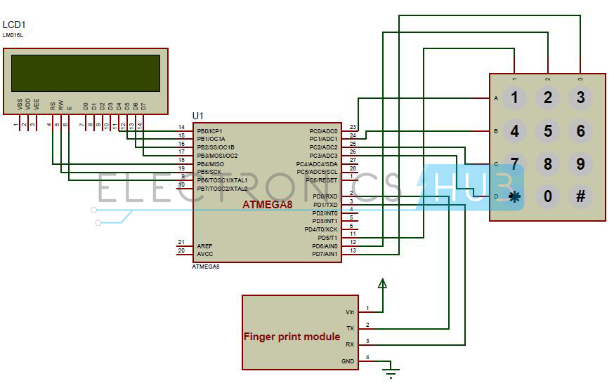
Biometric Attendance System Circuit Diagram:
Circuit Components:
- AVR microcontroller development board.
- Fingerprint module R305.
- Keypad (4*3).
- Atmega8 microcontroller
- RS232 Serial cable.
- DC Battery or Adaptor (12V, 1Amp).
- 16*2 Alpha Numeric LCD.
- Single pi connecting wires.
Biometric Attendance System Circuit Design:
Here, we used an ATmega8 microcontroller which is an AVR family microcontroller. It is 8 bit microcontroller and has 23 programmable input and output pins. It has 8 KB of flash memory, 512 bytes of EEPROM, 1KB of SRAM.
Biometric module used here is R305 series finger print module. It supports USART communication protocol. Here, USART protocol is used for communicating with the micro controller. USART is universal synchronous and asynchronous receiver and transmitter. This module has four pins out 1) Transmit, 2) Receive, 3) Vin, 4) GND. Transmit pin is connected to the receive pin of the microcontroller. Receive pin should be connected to the transmit pin of the microcontroller. Vin is applied with a voltage of 5V and GND is connected to ground. Data can be transmitted or received using serial communication.
Finger print processing involves two steps.1) finger enrollment and 2) finger matching. Initially, to enroll the finger user must give his finger print twice to the module. Module checks these two images and generates a template image and stores it. In the second step of finger matching, for 1:1 matching input finger print is matched with the template image generated and it generates an acknowledgement. For 1: N matching input is matched with the images in the library. It gives the matched image, a page id of the matched image is generated.
Keypad used in this project is 4*3 keypad i.e. it has four rows and three columns. Columns of the keypad are connected to the PORT D pins of the microcontroller. PD5 to PD7 pins are connected to the three columns of the keypad. Rows are connected to the PORT C of the microcontroller. PC0 to PC3 pins are connected to the rows of the keypad. To give attendance, press 1 from the keypad and to enroll press 2 from the keypad, to clear all the data press 3 from the keypad.
Liquid crystal display is used for displaying the messages. This is interfaced to PORTB of the micro controller. LCD in 4bit mode is connected to the micro controller. D4-D7 pins are connected to the PB0-PB3 pins of the microcontroller. RS pin is connected to the PB4, RW pin is connected to the PB5 and Enable pin is connected to the PB6 pin.
Working of Fingerprint Based Attendance System Circuit:
- Power the AVR development board.
- Burn the code into the microcontroller using serial cable.
- While burning the code make sure that slide switch is in programming mode.
- After burning the code switch off the supply and disconnect the serial cable.
- Now connect the circuit as shown in the diagram.
- LCD will display “Biometric Attendance System”.
- After sometime it will display a message “1.Attendance, 2.Save, 3.Clear”.
- Now press 1 from the keypad. It will take the attendance if you place your finger on the module. If your finger is not matched it will indicate the same.
- If you want to save your roll number press 2 from the keypad. It will ask you to enter the roll number and asks you to place your finger. After saving successfully your details it displays a message saved.
- To enroll again press 1 from the keypad and press 2 to exit.
- If you want to clear the data press 3 from keypad and enter the password.
Biometric Attendance System Circuit Applications:
- This can be used in educational institutions.
- Biometric attendance system can be used in industries.
- Biometrics can be used in ATM for authentication.
- Finger print authentication can be used in access control.
Limitations of the Circuit:
- There is a chance of misusing the technology by placing a fake finger print.
- Modules are sensitive and they need to be handled carefully.

58 Responses
Sir your circuit diagram seems to be made in proteus. If it is then how you got the finger print module in proteus.
please send it to my email:
hamid .safikhani@gmail.com
hello, i m interest for biometric attendence system please provide code..
Plzz send me a code for this project …
anybody having code of this
Please send me code of this project
hello, i m interest for biometric attendence system please provide code.
please provide me the code
Dear sir,
Kindly send me the code and circuit diagram to my mail @ gourabagrawal@gmail.com. Thanks in Advance.
is this project can be complete by using 8051 mc,instead of atmega8 mc
i am interest in this projects so please send me this projects code…..
Dear Sir,
kindly plz send me the code and ckt diagram to my mail sattirupeshreddy@gmail.com
Thanks u sir in advance
I am interest on this project so please send the code to srinivasannkece@gmail.com
Dear sir,
Kindly send me the code and circuit diagram to my mail @
aidanordin1sss@gmail.com
Thanks in advance.
I want the code please
Please send me a code of this project
sir, pls kindly send me the code and the circuit to my email am having problem with my project.
pls send the code plsss
mail me the code on
please do it soon..
thanks
please send me the code
Very interested in this project for my students. please send me the code for the project to this email tkwantwi@umat.edu.gh
I am interested in doing this.
Please provide me with the code.
thank u for sharing this,could u send the whole project work to my e mail,i will most grateful!!.
Plzz send me a code for this project …
Pls send me code for this project
Your work is great . Could you please send me the code for this.
plz send the me the code
Please send the code for this project
im intrested on this project
Very interested in this project for my students. please send me the code for the project to this email
If u have code plss send me
It is very important to me .so if you can send code.
We will provide it soon
Please send me the code
sir,please email me the code soon this is my semester project
Sir i need code of this project….i will be very thankfull to u you sir
send me code please
send me code pls
Can I please get this code. tasmiya117@gmail.com
Wonderful project sir.
Sir please am interested in the biometrics attendance project. Please send me the code at laralawal2y14@gmail.com. awaiting your reply sir. Thank you
excuse me, i’m taking interest in studying this. if i may, can i ask for the code? please send it to my email. i’ll appreciate it if you can send it
R u received the code
sir. this Project was approved as my Project Topic, in which i will start construction soon. So i need the CODE and i will be very happy to have it
Plssss provide me the code
This work is great
Kindly send me the code
Thankw
how can we do this using iris scanner ?
Hi . A nice project this is , i would like to give improvements to this project and make it more enhanced with current resources. please provide the code.
Please I need d code
U r doing great job.. It is very helpful for engg students who are searching for ideas…. Please provide me a code ..
I love the project.
I’m interested in it please send me the whole project details including the code
Kindly send me your perfect project coding, Just for study with your nice project,
I am fully interested to do this project
Plz……. Send me the code.
I am too much interested to do this project.
please send me the code.
I’m interested in biometric attendence system project please send me the code!
Sir I need code for this
Kindly send the code. I am very interested in making this project
Can someone send me the code of this?
i am interested on this project sir please provide code