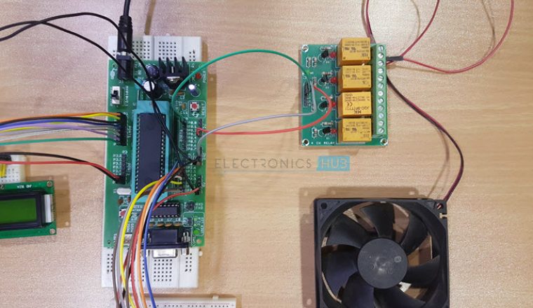
A Temperature Controlled DC Fan is a system which automatically turns on a DC Fan when the ambient temperature increases above a certain limit.
Generally, electronic devices produce more heat. So this heat should be reduced in order to protect the device. There are many ways to reduce this heat. One way is to switch on the fan spontaneously.
This article describes two such circuits that automatically, switches the fan when it detects the temperature inside the device greater than its threshold value.
Temperature Controlled DC Fan using Microcontroller
Output Video
Circuit 1 Temperature Controlled DC Fan using 8051
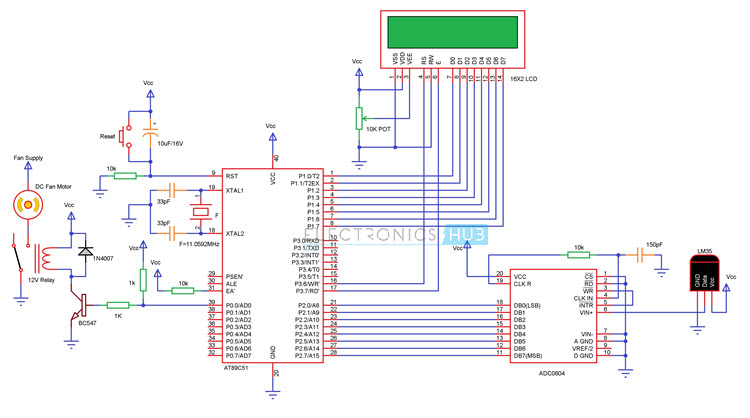
Circuit Diagram
Principle
The project works on the principle of Analog to Digital Conversion. The Analog data from the LM35 temperature sensor is given to the analog to digital converter ADC0804.
The analog output of the temperature sensor will vary at 10mV per degree Celsius.
ADC0804 is an 8-bit ADC. For a reference voltage of 5V, we’ll get a resolution of 5V/28 = 20mV. Which means, this is the minimum change in the analog value from the sensor which is recognisable by the ADC IC.
As per the changes in the temperature, the output of the ADC is generated. The digital output of the ADC is given to Microcontroller to calculate the temperature and control the fan accordingly.
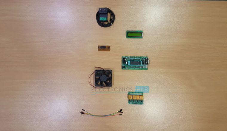
Components
Microcontroller Section
- AT89C51 Microcontroller
- AT89C51 Programmer Board
- 11.0592 MHz Quartz Crystal
- 33pF Ceramic Capacitor
- 2 x 10KΩ Resistor
- 10µF Electrolytic Capacitor
- Push Button
- 16 X 2 LCD Display
- 10KΩ POT
Temperature Sensor Section
- LM35
- ADC0804
- 10KΩ Resistor
- 150pF Ceramic Capacitor
- 1KΩ x 8 Resistor Pack
Load Section
- 2N2222 NPN Transistor
- 1N4007 Diode
- 12V Relay
- 1KΩ Resistor
- Fan
Configuring ADC0804 for this Project
The configuration of the ADC0804 is explained here. First, we need to connect the 5V regulated power supply to the Vcc pin (Pin 20). Then, connect the analog and digital ground pins (Pins 8 and 10) to the GND.
In order to use the internal clock, we need to connect a 10KΩ resistor between CLK IN (Pin 4 and CLK R (Pin 19) and then, connect a 150pF cap between pins 4 and GND to complete the oscillator circuit.
The CS pin (Pin 1) is connected to GND to enable the ADC.
In order to read the data from the ADC continuously by the microcontroller, we need to connect the RD pin (Pin 2) to the GND.
For the ADC to continuously read the analog data from the sensor, we need to short the Write pin (Pin 3) with the Interrupt pin (Pin 5).
The analog output of the sensor (LM35) is connected to the Vin+ (Pin 6) of the ADC. The negative analog input pin i.e. Vin- of the ADC is connected to the GND.
The converted digital data which is an 8-bit data will be available at DB0 to DB7 (Pins 18 to 11).
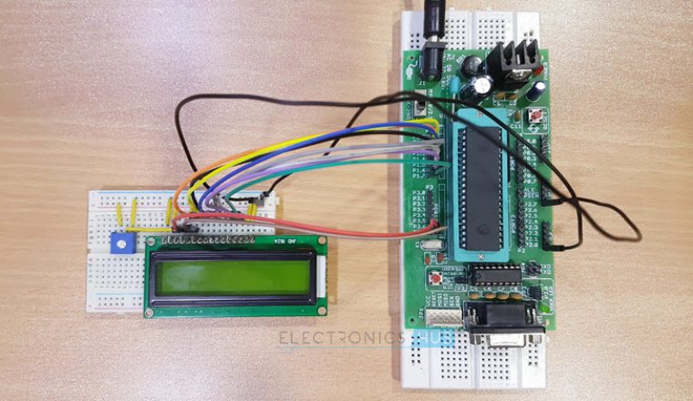
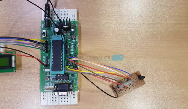
Circuit Design
The main components of the project are 8051 Microcontroller, 16×2 LCD Display, LM35 Temperature Sensor, ADC0804, Relay and Fan.
The basic connections with respect to microcontroller include clock, reset and EA. Clock consists of an 11.0592 MHz crystal and two 33pF capacitors. The reset circuit consists of a 10µF capacitor, 10KΩ resistor and a push button. The EA pin is pulled high with a 10KΩ resistor.
Now we’ll see the connections with respect to other components.
For the LCD display, a 10KΩ pot is connected to contrast adjust pin. The three control pins of the LCD are connected to the pins P3.6, GND and P3.7.
The 8 data pins of the LCD are connected to PORT1 of the microcontroller.
The basic connections with respect to ADC are explained in its configuration. The 8 digital outputs of the ADC must be connected to PORT 2 of the microcontroller.
The next component we are going to connect is LM35. Connect the data pin of the LM35 to the analog input pin i.e. Pin 6 of ADC.
Finally, we need to connect the Relay circuit consisting of resistor, transistor and relay to the PORT0 of the microcontroller with PORT 0 pulled-up externally.
Connect the input of relay i.e. base of the transistor to P0.0 pin of the microcontroller.
Working
The aim of this project is to design a temperature controlled fan using 8051 microcontroller, in which the fan is automatically turned ON or OFF according to the temperature. The working of the project is explained here.
In this circuit, the LM35 temperature sensor will give continuous analog output corresponding to the temperature sensed by it. This analog signal is given to the ADC, which converts the analog values to digital values.
The digital output of the ADC is equivalent to sensed analog voltage.
In order to get the temperature from the sensed analog voltage, we need to perform some calculations in the programming for the microcontroller.
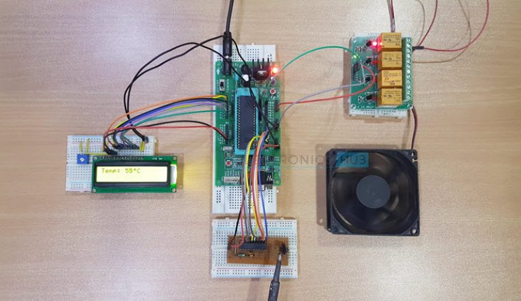
Once the calculations are done by the microcontroller according to the logic, the temperature is displayed on the LCD. Like this, the microcontroller will continuously monitor the temperature.
If the temperature exceeds more than 50 deg Celsius (as per the code), the microcontroller will turn on the relay to start the fan. If the temperature drops below 40 deg Celsius (as per the code).
DOWNLOAD PROJECT CODE
Circuit 2 Temperature Controlled DC Fan using ATmega8
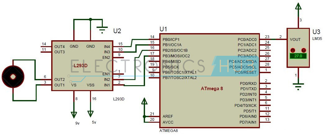
Circuit Diagram
Circuit Principle
The main principle of the circuit is to switch on the fan connected to DC motor when the temperature is greater than a threshold value.
The microcontroller continuously reads temperature from its surroundings. The temperature sensor acts as a transducer and converts the sensed temperature to electrical value. This is analog value which is applied to the ADC pin of the microcontroller.
The ATmega8 microcontroller has six multiplexed ADC channels with 10 bit resolution. The analog value is applied to one of the input ADC pins. Thus conversion occurs internally using successive approximation method.
For ADC conversion, internal registers should be declared. The ADC pin outputs a digital value. This is compared with the threshold value by the controller which switches the fan if value is greater than threshold.
Do you know about The Working of Stepper Motor Control Circuit using 8051 Microcontroller?
Components
- Atmega8
- L293D
- Lm35
- DC motor
Component Description
LM35
The LM35 is an integrated circuit sensor that can be used to measure temperature. The output voltage of this sensor is proportional to the temperature in degree Centigrade. The output voltage of the LM35 will vary at a rate of 10mV per degree Celsius.
Usually, the range of the LM35 temperature sensor is from -55 deg C to +150 deg C. To measure this full range of temperatures i.e. from negative range to positive range, we need to connect an external resistor between the data pin and a negative supply of Vcc.
Any way, we are not going to consider the negative temperature range in this project. So, under normal operating conditions, we can measure the temperature in the range from +2 deg C to +150 deg C.
ADC
All the parameters of nature are of analog i.e. most of the data in the real world is characterised by analog signals. For instance, if the temperature of the room is measured.
The room temperature varies with time continuously. This measured signal, which continuously changes with time say from 1sec , 1.1sec , 1.2 sec and so on is called Analog signal.
In order to manipulate the real world data using a microprocessor or a microcontroller, we need to convert the analog signals to the digital signals, so that the processor or controller will be able to read, understand and manipulate the data.
Atmega8 has internal Analog to digital converter.
Declaring of internal ADC Registers
- The ATmega8 microcontroller internally has three register namely ADMUX , ADCSRA, ADC data registers. Analog to digital converter is of 10 bit resolution.
- Initially, select the reference voltage to the ADC using ADCMUX register.
- Select REFS0 and REFS1 values in ADMUX register to set the reference voltage.
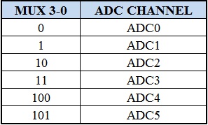
- Now select the ADC channel using MUX0-MUX3 bits in ADMUX register. Below given table shows the binary value to be placed in the MUX0-MUX3 bits to select a channel.
- If the sensor is connected to ADC0 channel with AVCC with external capacitor at AREF pin, then the binary value to be assigned to the ADMUX register is ADMUX=0b01000000.
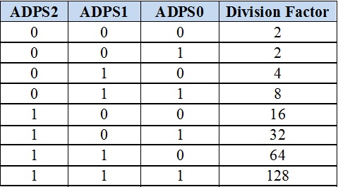
- Now select the pre scalar value using ADPS0, ADPS1 and ADPS2 bits of ADCSRA register and also enable ADC using ADEN bit in ADSCRA register.
- The following bits decide the division factor between XTAL frequency and input clock of ADC:
- Now enable start conversion bit that is ADCSC in ADCSRA register.
- After the conversion of the value, an interrupt bit is enabled by the hardware
- Wait until interrupt bit ADIF is set to 1.
The result is stored in two data register of ADC that is ADCL and ADCH. Now read the digital value from these registers
Temperature Controlled DC Fan Circuit Design
The circuit mainly consists of ATmega8 microcontroller, temperature sensor, DC motor, driver IC. Temperature sensor is connected to the input of the ADC pin i.e. ADC0 pin of the microcontroller.
Temperature sensor has three input pins, VCC, ground. Middle one is output and the other two pins are ground and VCC. VREF and AVCC for the ADC are applied externally to the microcontroller. Pin 20 and 21 are AREF and AVCC pins connected to the supply voltage of 5v.
Port B of the microcontroller is connected to the motors through a motor driver IC i.e. L293D. Input pins of the motor driver are connected to the microcontroller. PB0 and PB1 are connected to the input 3 and input 4 of the motor driver IC.
PB2 and PB3 pins are connected to the input1 and input2 of the motor driver IC. Output pins are connected to the motor. As the motor has two pins, these are connected to the output pins of the driver IC.
Temperature Controlling DC Motor – Circuit Simulation Video
How Temperature Controlled DC Fan Circuit using Microcontroller Works?
- Initially switch the power supply.
- Microcontroller starts reading the temperature of the surroundings.
- The analog value of temperature is given by the temperature sensor.
- This analog value is applied to the analog to digital converter pin of the micro controller.
- This analog value is converted to the digital value by the microcontroller using successive approximation method internally.
- When the temperature is greater than the threshold value, microcontroller sends a command to the controller to switch the motor.
- Thus fan starts rotating.
Temperature Controlled DC Motor Project Output Video
Applications
- Temperature Controlled DC Fan can be used to control the temperature of devices, rooms, electronic components etc. by monitoring the temperature.
- Can be extended to PWM based output, where the speed of the fan can be varied according to the duty cycle of the PWM signal.
- The circuit can be used in CPU to reduce the heat.

51 Responses
can I test this ckt
Can you mail me the hex file of Temperature Controlled DC Fan using Micro controllers project Thanks.
hi..
can i know what software are u using for demonstrate the circuit…
hope fully u can reply me ASAP
Want to know how to use this on an airconditioner. And from the circuit diagram, is that all i need to build this circuit
Hello I’m thinking to do this project but with some improvement.Do you have an advise how to improve the system in term of application???If can the improvement will not change much the circuit design.For example if we add other function into the circuit,does it will change the overall components??
how the circuit is prepared
what are the components fixed on circuit board with their numbers
You can find the components in the circuit diagram..Here Atmega8 microntoller,LM35 temperature sensor,L293d Motor Driver and motor were used..
please enter every part of circuit
i m making same project for my home………i need code for it…..n evry info abt ths proect…kindly mail me info about this project
I require the project “temperature controlled dc fan using microcontroller” se nd the details
i require this project. Send me the details of “DC Fan controlled by microcontroller. “
Bro Could you Send me the code ?? urgently !
Please go through the article.Code is uploaded..
I couldnt find the code can u please send me the code
I Wanna this code because im gonna make this project for my home
Please Send it to me Urgently !
Thanks
I want to make this same project in school,,pls send me the code and procedures to follow
I need this project’s code because I’m making the same project for my TE mini project. I like this project’s application.
I need the help of this project to complete my minor project.
I’m trying to make a different project.
My project name: Micro controller based automatic fan speed regulator using temperature sensor
Abstract: In this project, a temperature sensor (LM 35) is used which senses any slight
change in room temperature and sends it to Analog to Digital Converter to get the
digital equivalent signal. The output of the (ADC) is directly connected to the
Microcontroller which controls the desired system i.e to regulate the speed of the
fan. Also, the sensed room temperature will be displayed on LCD display.
Please send all the details about this project including circuit, design, etcra
wheres the component list?? i need the list to do it -.-
You can find the required components in the circuit diagram..
Am very interested in this your project. So I want used the same circuit sa my final year project. Thanks
I am very interested with project.in my IT place, we constructed one circuit related to this .so,I want to do it in my final year project. I am now in final year. pls help urgently with it code.
I need to do the same project with some improvement pls send me the code
I found this project interesting! Kudos to you!
Need complete details of this project as I have to make a mini project (college purpose)
Hope you’ll provide me with the details
Hi,
I am looking for projects to carry out for my college work and this was one was the most appealing one to me. May I please have the code and any other important information about this project emailed to me? Thank you.
Please go through the article completely…You can download the code
Hi,
I am looking for projects to carry out for my college and this one was the most appealing to me. May I please have to code and any other important information emailed to me?
Thank you
Code is uploaded in the article.You can download it from there
I’m doing this same project for my diploma final year mini project please send me code . Please sir. I’m doing it without any support from project centre. Help me sir
Code is uploaded in the article..Go through the article completely..If you need any further help you can contact us..
can you give the full code?not separated code,because i feel confuse with that code
Thanks for all the information and the proposal. I am interested by these project. Please share me the code via email
please send to me the matlab and its full information about this project ?i am doing that for semester project.
Hello someone please I need the hex file for temperature control dc fan for my diploma final project. someone please i really need it. 🙁
Can we do the same project using at89c51 instead of atmega?
Yess you can do..
yess
I m doing this project for my mini project… I need the program and code for this project… Can u please mail me…
can u send me program for automatic fan speed controller using 8051
I’m not able to make payment through my debit card
Is credit card necessary
Hi,Please mail to elktros@gmail.com..My team will help you..
Hello sir /mam
Please give the program code ..
what is the block diagram of the controlling temperature of the dc motor
What is square box named ‘F’ in the first circuit diagram
Sorry. That is the crystal oscillator of frequency 11.0592MHz. Might have missed it while designing.
very useful this controlling temperature in dc control
Sir how much it will cost to design the project . I am opening a small unit of exhaust fan so I want to introduce this to that exhaust fan so could you help me with the details and will it be feasible.
It’s very good and very helpful for my on going project. thank you very much….
please can i get the code for this project the link is not working