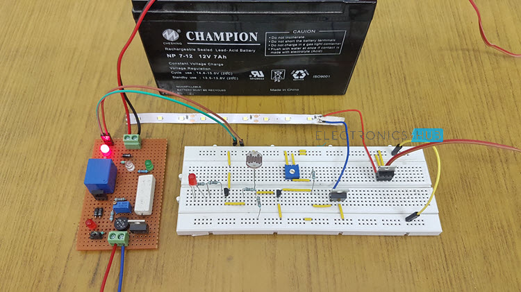
This is the simple and cost effective automatic LED Emergency Light Circuit with light sensing. This system charges from main supply and gets activated when main supply is turned OFF. This emergency lamp will work for more than 8 hours (depending the battery capacity and the power consumed by the LEDs).
When power supply is turned OFF, the circuit senses the day light and according to the light it turns on the LED’s. If the light is present even though power fails the circuit turns OFF the LEDs. Here LDR (Light Dependent Resistor) is used to sense the light.
Automatic Emergency Light Circuit Principle
When power supply is available, battery charges through the battery charging circuit. When the power fails, the white LED’s which are connected MOSFET will glow based on the light condition till the battery shuts down.
When LDR (Light Dependent Resistor) is in light, the resistance of LDR is very low. As a result base of the transistor Q2 becomes high. As a result white LED’s which are connected to MOSFET turns OFF.
When the circuit is in dark, the resistance of LDR is in order of mega ohms. Now the base of the transistor becomes low, as a result transistor Q2 switches the white LED’s to ON state.
Also read the related post: Automatic Washroom Light Switch Circuit
Automatic Emergency Light Circuit Diagram
I have divided the circuit into two parts. The first one is the battery charging circuit which also acts as an indicator circuit if the mains supply is shut down. The second circuit is the emergency lights circuit using LEDs. Based on the mains supply and the lighting conditions, the emergency LEDs are turned ON or OFF.
Battery Charging Circuit
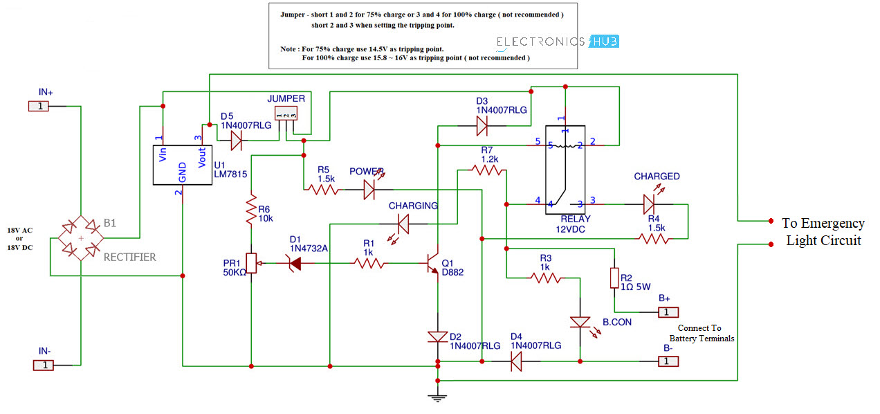
The components, working and connections are explained in this Lead Acid Battery Charger Circuit.
Coming to the Automatic LED Emergency Light Circuit, the following is the circuit diagram.
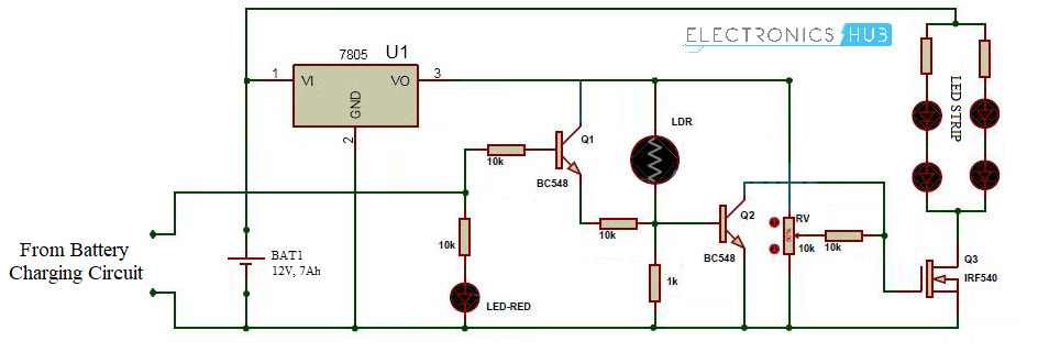
Components for Automatic LED Emergency Light Circuit
- 7805 voltage regulator
- Light Dependent Resistor – 2MΩ
- IRF540 MOSFET
- BC548 NPN Transistor
- Pot – 10KΩ
- High bright LEDs – 3V@15mA
- Red LED – 1
- 10KΩ Resistors – 3
- 1KΩ Resistor – 1
Working of Automatic Emergency Light Circuit
Initially, when the mains power is active, the battery charging circuit will charge the battery. In case the mains power is shut down, the battery charger circuit indicates the Emergency Light circuit about mains power and activates the emergency lights circuits through the battery.
Instead of immediately turning ON the LEDs, it first reads the ambient lighting through the LDR and then if the lighting is low, the LEDs are turned ON.
How to Operate Automatic Emergency Light Circuit?
- Give the connections according to the circuit diagram.
- While giving the connections, take care in such a way that there is no common connection between AC and DC supplies.
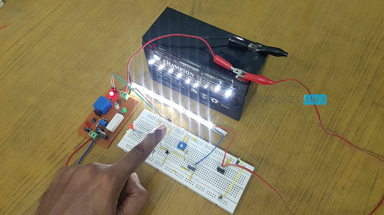
- Apply the main supply to the circuit, now you can observe that LED’s will not glow and battery will charge.
- Remove the AC supply and place circuit in dark, now LED’s will glow.
- If you place the circuit in light, then LED’s turns OFF.
Advantages of Automatic Emergency Light Circuit
- This is very simple circuit and the cost is also very less.
- Power is saved because the circuit switches the LEDs based on light conditions
Automatic Emergency Light Circuit Applications
- Used in child’s study rooms to avoid the sudden power failure.
- As an emergency lamp in homes.
- Used in security systems to switch ON the lights automatically during the power failure.
Emergency Light With Battery Charger
A very easy circuit of “variable power supply and charger” is being explained here. It is not only very much useful in the time of power cut but also used as main power supply. At your workbench, you can use this circuit to check or testing of your electronic projects. Mobile phone batteries can be charged with the help of these circuits. This circuit can work as an emergency light.
Circuit Diagram
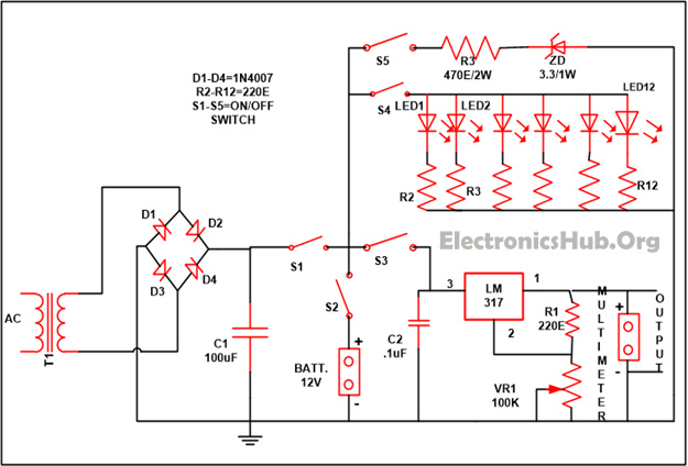
Circuit Components
- LM317 – 1
- Resistor
- R1 (220E) – 1
- R2-R12 (220E) – 11
- R13 (470E)
- VR1 (100K) – 1
- C1 (100uF) – 1
- C2 (. 1uF) – 1
- D1-D4 (1N4007) – 4
- S1-S5 (on/off switch) – 5
- LED1-LED12 – 12
- Transformer – 1
- Battery – 1
- Zener diode (3.3) – 1
Components Description
- LM317: It is a variable voltage supplier. It is a device with three terminals. It works on voltage range of 1.25 V to 37 V at a current of 1.5 amps.
- Resistor– The flow of current in any of the circuit is being controlled by the resistor. It is basically a passive device. There are two types of resistor available i.e
- Fixed Resistor – whose value of resistance is fixed
- Variable Resistor – whose value of resistance can vary
- Capacitor– It is used to store the electrical charges . It is also a passive device and are available in the market in two types i.e.
- Polarized Capacitor – Capacitors with polarity i.e. have + and – terminal eg electrolytic capacitor
- Non-Polarized Capacitor – Capacitor without any polarity e.g. ceramic and paper capacitor.
- Diode – It is mainly used to allow the single directional flow of current. It is a passive device with two terminals.
- Switches -Literal sense of a switch is “transform of state”. In an electrical logic, ON and OFF are the two conditions and switch assist to alter the condition of an electrical machine from ON to OFF or reverse. Firmly talking, it doesn’t turn on or off the machine; it merely creates or break the contact.
- LED (Light emitting diode) – It is a semiconductor device that produces a diverse source of beam at its output. When they are electrically biased in the forward state of p-n junction it emits a narrow spectrum of light. LED are found in the market very easily in a variety of colors via red, yellow, green and many more like white, orange etc.
- Transformer -A transformer is a device which is used for transforming current from one circuit to another. During the transformation process, characteristic of AC signal changes. For example a low voltage AC may be changed to a high voltage AC and vice versa. The working of the transformer is based on the magnetic field to build around the conductor when current flows through it. This principle is called as electromagnetic mutual induction. Transformers are made up of two coils of wire wrapped around a core.
- Battery – Battery is mainly a group of one or more than one electrochemical cell and in that chemical energy that is already stored is turned into electrical energy. From the age of Volta the principles of operation have not been altered. Every cell in the battery is made up of two halves of cells which are linked in series via an electrolytic solution. While 1/3 of the cell is made up of two houses named as the anode and cathode positive ions of the anode roam from the electrolyte to the cathode.
- Zener Diode – This diode work in the reverse bias state and start conducting when the voltage achieves the break point. If you want to get stable voltage then all you need is to couple a resistor across it so that current flow can control.
Working of Mobile Phone Battery Charger Circuit
As per your need you can take the output from the circuit by just flipping the different number of switches (from S3, S4 and S5) in the circuit.
If you require the variable power supply as your output than set switch S3 into “on” state. LM317 is used in the circuit which is a variable voltage regulator to supply variable power.
The LM317 is basically positive voltage regulator has three terminals. 1.2 V to 37V is the range of the output voltage that is provided by the LM317.
Different range of voltage can be achieved by just adjusting the variable resistor that is provided in the circuit and with the help of multimeter output can be seen and the voltage which is desirable can set. The power supply range can altar from 1.5V to 12V.
Related Post:USB Mobile Phone Charger Circuit Diagram
With the help of flipping the S5 switch which is provided in the circuit Li-ions battery can be charged, which are generally used in the mobile phones with the assist of your mobile connectors.
While the charging current in the circuit is being controlled with the help of resistor R13. Turn over to switch S5 if you want to use the emergency light. Reflectors can be used in the circuit if you wish to enlarge the intensity of light.
S1 and S2 are the two switches that are given in the circuit so that you can power your circuit either directly with the AC supply or else you can take help of any battery.
If you want to use an AC supply than flip to switch S1 while if you want to have supplied from the battery than flip to switch S2. In the place of AC power supply solar panels can be used and for storing the charge you can take rechargeable batteries, this will not merely save electric bill but also assist you a

14 Responses
plz send mi the pcb layout of this project…
I’m doing automatic LED emergency light using LDR…
but I cant make the layout… plz tell… Its an emergency…. plz…
I’m making one of this… plz send me pcb layout… Its urjunt…
can i implement this project by using solar panel ???? if yes plz provide me circuit diagram and layout of this project……….plz its urgent………..plz…….plz
Yess..Simply connect the solar panel before 7805 instead of bridge rectifier and transformer….make sure voltage of the panel is around 7-8volts minimum..
I’ve followed the circuit diagram, but the LEDs only turn on when i shine a light on the LDR, but the LEDs won’t come on in the dark, could there be anything causing this?
I am trying to make this type of project but can’t succeeded so kindly send me layout of this project plz plz………………….
Are 4 LEDs light enough for a room? If not, can we have few more LEDs added to this circuit?
If u need more brightness you can increase number of Leds…
for how many duration the battery has to be charged
i am doing automatic LED emergency ligh using ldr….plz send me the pcb layout…plz
am in the process of making this project,provide block diagram please
Why can’t my circuit work? Every time it burns either the components or the breadboard.. so frustrating man! Even tried only with the battery but i didn’t work too. What is wrong with my circuit? Need help please.
am done with this my project construction.
I only need the write up.
can you help me?
LED Base Automatic Emergency Lighting system using LDR and a 6 volt battery.
thanks
Why does everyone seem to need a PCB lay out ??? That’s crazy …. Have you ever done this sort of thing before or do you need everything spelled out in redundant details ??? Be creative learn what your doing and if it really is an emergency get a flash light …. My word so many lost people