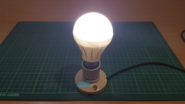
LED Light bulbs are becoming more common and are replacing the CFL Bulbs. With the cost of LED light bulbs becoming lower, people are gradually shifting towards LED Lamps in their homes and offices. In this project, we will try to make a DIY LED Light Bulb or a DIY LED Lamp using an old LED Lamp housing (case).
Outline
ToggleDIY LED Light Bulb (LED Lamp)
In this DIY LED Light Bulb, the design of the LED Driver is very important. Generally, we have two ways of designing the LED Driver: using a Switching mode power supply or a regular transformer based linear regulator.
But for this DIY LED light bulb, we will be designing a transformer less power supply to act as the LED Driver. In fact, this type of power supply for LED Lamps is becoming more common (well, at least for lower wattage LEDs).
Warning: This DIY LED Light Bulb will work directly from the main supply i.e. 230V AC. You need to be very careful when working on AC Supply.
Warning: Designing Transformer less power supply without the knowledge of how the components work can be fatal.
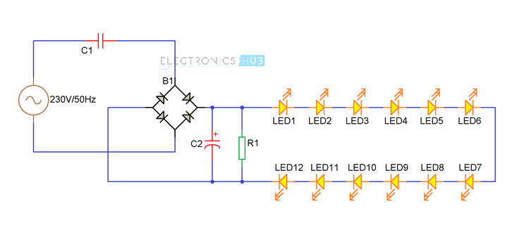
DIY LED Light Bulb Circuit Diagram
Components Required for DIY LED Light Bulb
- C1 – 135J 400V Metal Film Capacitor
- B1 – Bridge Rectifier (4 Diodes can be connected in Full wave Rectifier mode)
- C2 – 22µF 35V Electrolytic Capacitor
- R1 – 100KΩ Resistor (1/4 Watt)
- LED 1 to 12 – 8mm LEDs
NOTE: Use only metal film capacitor rated greater than equal to 400 for C1.
Component Description
X – Rated Capacitor
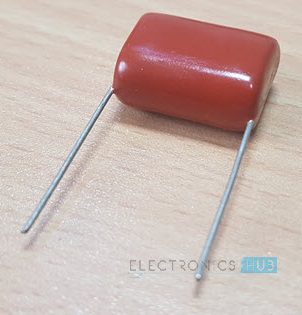
The main component of the Transformer Less Power Supply Design for the DIY LED Light Bulb is the X – Rated Capacitor. It is a metal film capacitor that is often used as a safety capacitor.
An X – Rated capacitor is placed between the line and neutral. If this capacitor fails due to overvoltage, the fail will be a short and the excess current will blow the fuse and hence avoiding any electrical shocks.
Circuit Design of DIY LED Light Bulb
First, the main supply is given to the metal film capacitor. The other end of the capacitor is connected to the AC input of a bridge rectifier. To be on a safer side, connect a 100Ω 1W Resistor in series with the X – Rated Capacitor to act as a fuse (not shown in the circuit).
NOTE: If you do not have a bridge rectifier, you can connect 4 PN Junction Diodes (like 1N4007) in full wave rectifier mode.
The other AC Input of the Bridge Rectifier is connected to the Neutral of the AC Power Supply. The rectified output is given to a capacitor (C2). 12 8mm LEDs are connected in series across the capacitor.
The Resistor R1 will act as a bleeder resistor (it will discharge the capacitor in the event of power failure or if LED fails).
NOTE: We have disassembled a damaged LED light bulb and after reconstructing the circuit, it was similar to the one we have designed. The main difference is that they have used SMD Components for LEDs and Bridge and we have used through–hole components (for obvious reasons).
PCB Design of DIY LED Light Bulb
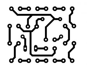
In order to design the PCB Layout of the LED Light Bulb, we have used the Eagle CAD. The following image shows the PCB Layout of the LED Light bulb. We have made the PCB using Toner Transfer Method as mentioned in this tutorial: How to make your Own PCB at Home.
Assembling the LED Light Bulb
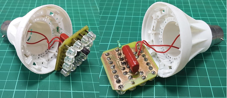
Assemble all the components as per the layout and solder them. We have got an empty LED Housing from an old LED Lamp. After assembling the PCB, we mounted the board in the LED Housing with all the wires.
Working of the LED Light Bulb
Now, we will see the working of this simple DIY LED Light Bulb.
LEDs need very less current in order to work. Normally, in a regular transformer based regulated power supply, we will regulate control the current with the help of series resistors. But in the transformer less power supply, the current is controlled or limited by the X – Rated Capacitor.
Since, this capacitor is connected in series with the AC Supply, the total current available in the circuit is limited by the reactance of the capacitor.
The reactance of a capacitor can be calculated using the following formula:
XC = 1/2πFC Ohms, where F is the frequency of the supply, C is the capacitance of the capacitor.
In our case, we have used a 1.3µF Capacitor. Hence, the reactance of this capacitor is
XC1 = 1 / (2*π*50*1.3*10-6) = 2449.7 ≈ 2450 Ω.
Therefore, the current through this capacitor is given by I = V / XC1 Amps = 230 / 2450 = 93.8mA.
Now, the current limited AC is given to the Bridge Rectifier. The output of the bridge will be 230V DC. This is given to a filter capacitor of rating 35V. But the peak to peak ripple voltage across the Capacitor C2 is around 44V.
This is given to 12 LEDs in series and hence each LED will take up around 3.7V, which is equal to the rated voltage of the 8mm LED.
As far as the power is concerned, the total power output by the LEDs is around 4W.
Important Note: This project is just a demonstration of How to design an LED Light Bulb and How an LED Light Bulb works. The method mentioned in this project might not be suitable for practical usage.
Also, the project involves working around 230V AC Mains Supply. You need to be extremely careful when working with AC Supply.


5 Responses
Good
Has any relation with the input current of ac main
If i assembled the complete circuit, can this work regularly i.e. at least 5/6 months please intimate.
I do not understand the purpose of R1….. you mentioned it acts as a bleeder resistor, nice joke by the way… if LEDs fail, R1 and C2 will get huge voltages, C2 will take just fraction of a second to burst…and R1 with 1/4 wattage will also burn very nicely.
Also C2 is mentioned 35volt… and you are telling us voltage of each LED will be around 3.7V, so for 12 LEDs, it becomes almost 44 volts… C2 will not withstand it for long… please stop makin funny circuits without mentioning it… specially when working with AC mains…
did you miss C1?,
what’s funny about a bleed resistor
the likely hood of all the LEDs failing in remote..
What difference does the volyage of the LED make to C2 it just won’t drive them at full intensity?