Have you ever tried to design a battery charger which charges the battery automatically when battery voltage is below the specified voltage? This article explains you how to design an automatic battery charger.
Below charger automatically shut off the charging process when battery attains full charge. This prevents the deep charge of the battery. If the battery voltage is below the 12V, then circuit automatically charges the battery.
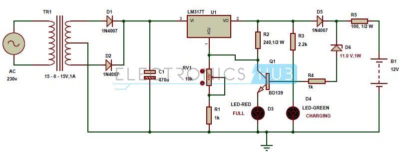
Automatic 12v Battery Charger Circuit Diagram
This automatic battery charger circuit is mainly involves two sections – power supply section and load comparison section.
The main supply voltage 230V, 50Hz is connected to the primary winding of the center tapped transformer to step down the voltage to 15-0-15V.
The output of the transformer is connected to the Diodes D1, D2. Here diodes D1, D2 are used to convert low AC voltage to pulsating DC voltage. This process is also called as rectification. The pulsating DC voltage is applied to the 470uF capacitor to remove the AC ripples.
Thus the output of the capacitor unregulated Dc voltage. This unregulated DC voltage is now applied to the LM317 variable voltage regulator to provide regulated DC voltage.
The output voltage of this voltage regulator is variable from 1.2V to 37V and the maximum output current from this IC is 1.5A. The output voltage of this voltage regulator is varied by varying the pot 10k which is connected to the adjust pin of LM317.
[Also Read: How To Make an Adjustable Timer ]
Lm317 voltage regulator output is applied to the battery through the diode D5 and resistor R5. Here diode D5 is used to avoid the discharge of battery when main supply fails.
When battery charges fully, the zener diode D6 which connected in reverse bias conducts. Now base of BD139 NPN transistor gets the current through the zener so that the total current is grounded.
In this circuit green LED is used for indicating the charge of the battery. Resistor R3 is used to protect the green LED from high voltages.
Output Video:
Circuit Principle
If the battery voltage is below 12V, then the current from LM317 IC flows through the resistor R5 and diode D5 to the battery. At this time zener diode D6 will not conduct because battery takes all the current for charging.
When the battery voltage rises to 13.5V, the current flow to the battery stops and zener diode gets the sufficient breakdown voltage and it allows the current through it.
Now the base of the transistor gets the sufficient current to turn on so that the output current from LM317 voltage regulator is grounded through the transistor Q1. As a result Red LED indicates the full of charge.
Charger settings
The output voltage of the battery charger should be less than 1.5 times of the battery and the current of the charger should be 10% of the battery current. Battery charger should have over voltage protection, short circuit protection and reversed polarity protection.
NOTE: Also get an idea about how to build a battery charging level indicator circuit?
2.Automatic Battery Charger
Circuit Diagram
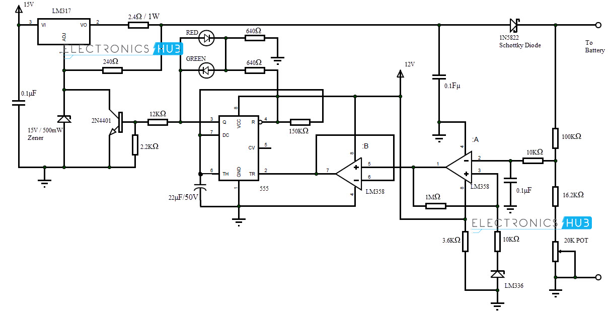
An Automatic Battery Charger Circuit for sealed lead acid batteries is mentioned in this project. It is a pulsed-charger type circuit which helps in increasing the life of batteries. The working of this circuit is explained below.
LM317 acts as voltage regulator and current controlling device. The 15V Zener diode is used to set the LM317 to supply 16.2V at output in the absence of load. When the 2N4401 is turned ON by the output of 555, the ADJ pin of the LM317 is grounded and its output voltage is 1.3V.
LM358 acts as a comparator and voltage follower. LM336 is used to supply a reference voltage of 2.5V to non-inverting terminal (Pin 3) of LM358. A voltage divider network is used to supply a portion of battery’s voltage to inverting terminal (Pin 2) of LM358.
When the charge in the battery reaches 14.5V, the input to inverting terminal of LM358 is slightly greater than 2.5V at Pin 3 set by LM336. This will make the output of 555 go high.
As a result Red LED glows and the transistor is turned on. This will ground the ADJ pin of LM317 and its output falls to 1.3V.
When the charge in the battery falls below 13.8V, the output of LM358 is high and the output of 555 is low. As a result, voltage flows from LM317 to battery and Green LED glows to indicate charging.
[Related Post– Lead Acid Battery Charger using LM317]
3.Battery charger Using SCR
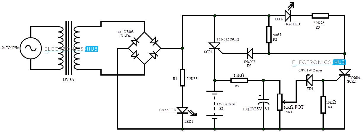
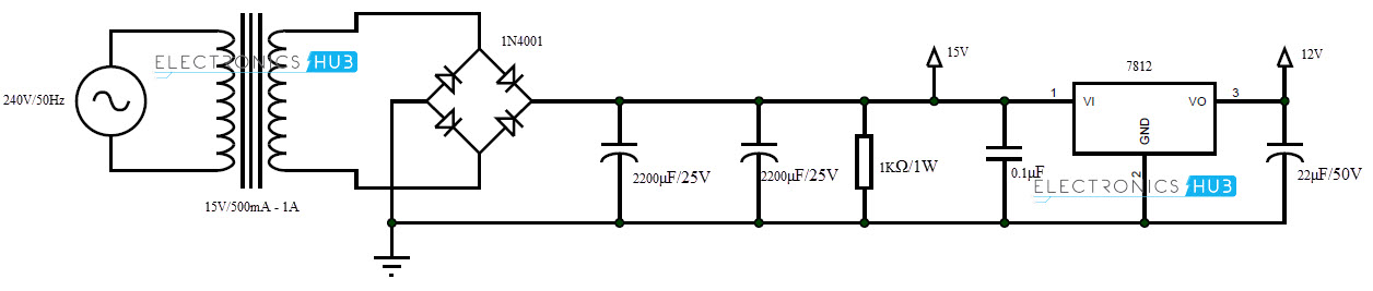
An automatic battery charger circuit using SCR is implemented in this project. It can be used to charge 12V batteries. Batteries with different potentials like 6V and 9V can also be charged by choosing appropriate components. The working of the circuit is as follows.
The AC supply is converted to 15V DC with the help of transformer and bridge rectifier and the Green LED is turned on. The DC output is a pulsating DC as there is no filter after the rectifier.
This is important as SCR stops conducting only when the supply voltage is 0 or disconnected from supply and it is possible only with pulsating DC.
Initially, SCR1 starts conducting as it receives a Gate voltage via R2 and D5. When SCR1 is conducting, 15V DC will flow through the battery and the battery starts to charge. When the charge on the battery is almost full, it opposes the flow of current and the current starts to flow via R5.
This is filtered with C1 and when the potential reaches 6.8V, Zener ZD1 starts conducting and supplies enough Gate voltage to SCR2 to turn it on.
As a result, the current flows through SCR2 via R2 and SCR1 is turned off as both gate voltage and supply voltage are cut off. The Red LED is turned on indicating a full charge on the battery.
Know how to design a circuit of auto cut-off and auto charging of a battery using SCR.

56 Responses
hi, i want to charge nokia bl-5c battery. i am using the same component, with accordingly adjusted values. my output is 5.22v, and 1.5 amp of current. if i will put my battery in charge forever with my application. then will there be any problem for explosion of the battery, and in that case what should be the value of the diode D6.
thanks in advance
please reply urgently
Hi to charge a 5 volt batt. All what you need is to change the circuit to 5 volt output and it come on different circuit. Your goal at that time is to maintain lower temperature which will not damage yr. Batt.
So different circuit is recommended.
1.5 amps for ur li-ion battery was very high. all u have to do is to reduce the current. according to ur circuit u dont want to worry about the voltage. becoz 5.22 v is safe to charge. just try to place a resistor before load to limit the current.
each and every battery has there own initial current value (charging current) u have to charge according to that unless u battery may explode.
“This circuit is tested in simulation software and may require some practical changes.”
Did someone build this charger & does it work OK?
Yes i did and work very good, no trouble at all.
did u simulate sir? and what software did u use?
Which kind of simulation software do you use ?
hey dude concept of circuit is cool but i think value of zener diode is less so breakdown early while switching on circuit can u please help me with your view my email address is kandelbishow@ymail.com
Hey. I have built your battery charger above but it did not work as it should for some reason. The green LED is constantly ON and the red LED is acting the same…
It must not work at all… I don’t know how people are appreciating this circuit… R5 is 100 ohm in series with battery???? 100 ohm x 1 Amp = 100 watt!!!!! whats left for the battery? and rating of that resistor is shown just 1/2 watt?????
kindly correct me if I am making any mistake to understand the circuit.
can this circuit use to charge mobile phone through usb?
No no no
Yes, but you need a new phone after.
Allah????? what ghylreat idea…
Nice circuit! thanks for sharing
i want to know…why in this charger uses lm317 voltage regulator …why other not..is it possible if iam using another voltage regulator..plz reply me
we are charging a 12 v battery here..so the output voltage should be between 14-16v..for that reason we have used LM317
I WANT TO USE THIS CIRCUIT FOR 10W20V SOLAR PANEL , I MEAN I WANT TO RECHARGE MY 12V9AH BATTERY BY USING SOLAR ! IS IT POSSIBLE?
In the scehmatics of LM317 based 1st Project, I am not able to locate POT, its connections and its value. I have noticed it only in video. Pleas help!
Please check below Lm317 IC ,there is 10k POT
I couldn’t get the POT working – the voltage control never worked. I always get around (Vin – 1.25) volts. Something seems wrong in the circuit.
I want high frequecy inverter circuit diagram
can i modify one of these circuits to charge a laptop lets apples laptop ?
Laptop battery need around 18-21 V at 3 to 4A. So these circuits would not be very useful. Laptop charging circuit can be designed using XL6009.
Hello brothers i got a question,my name is Austine from Tanzania i need to create an inverter thag can charge itself but i have no idea on how to make it becouse i have no circuit diagram of inverter, Charging system,Delay timer for switching on AC output, And battery voltage drop indicator/battery monitor
I made this circuit but it is giving max 8 v output
What should i do
Hi , I am just curious to know if this could be used to charge 2 12 volt slap batteries in series with the input voltage coming from the pedaling of a bicycle connected to a motor with the polarities reversed in order to create voltage. Would this be able to work if my input voltage to the circuit was a varying DC voltage?
Any help would be appreciated . I am trying to design a circuit to charge (2) 12 volt 10aH sla batteries using the power from bicycle pedaling,
In the battery charger Using SCR circuit above, wanted to clarify regarding the maximum current which would pass through SCR1. Assuming we are connecting a discharged Lead Acid battery. Then when the circuit is powered ON, the peak AC voltage at the anode of the SCR1 would be 21V (15V rms). This would forward bias the SCR1 since cathode is at zero voltage (as battery output is zero). The Gate of SCR1 is at higher potential than Cathode and hence SCR1 would conduct. At this stage since the internal resistance of a battery is in the range of 20-50 milli ohm. The current which would pass through SCR and battery as per Ohm’s law would be approx. 20V/20 milli ohm (assuming 1V drop across SCR in conduction phase). This would be a very large current which could potentially damage the SCR/battery. Is there something I am missing here?
Hi
Is there any way to change the minimum and maximum voltage of Battry???
Plz help me
pls help i want to use 6v battery what will i do
Can I use 12-0-12 transformer??
So this charger cuts the charging process until the battery discharges again or it stays charging the battery all the time to avoid several charge/discharge process?
I have connected everything correctly. However when I am connecting the battery green light is glowing and also both led is getting on when I am giving the power supply.
The output voltage is getting fixed to 8.9 however the lm 317 output voltage ig 22.1 Volt.
please check and help me with correct circuit and components.
Thanks
I built d circuit but on witching it on, both d green & d red leds were glowing. I adjusted d preset but no response. Pls, what do I do? Thanks.
Hello,
Thank you very much for sharing such knowledge.
I have tried cut-off with SCR but I have used
BUT12A instead os SCR. I also added Regulator with 7805 to the input of the Charger Using SCR circuit.
Now the 10K adjust the voltage very well but without SCR the red LED only turns off when it is higher than 13 V. I always use components from old electronic devices. I will try to charge my 12V battery from my wind tribune I have build with used electronic devices’ components.
Thank you for your time and interest.
I added a 4N35 to control the charge of my battery when there is no power from the wind and the sun. I can send you the circuit.
Thank you very much for such circuit giving me the chance to build my charge control.
This battery charger is safety or not?
And what is the function of the POT in the “Battery Charger Circuit using SCR”?
Please reply urgently, thank you,
Ah! I finally made the BD139 based circuit and as expected – IT DIDN’T WORK. The Pot did nothing to regulate the output voltage. Infact there is no way to regulate and measure the output voltage properly at ‘no load’ condition.
Hellow brother,can i use the circuit above to charge twelve volt battery and to supply my simple traffic light control system using timer and 4017 counter ic????
this website help me to 12 volt auto cut relly…..many thanks
hi
i need pcb…
help me
pleaseeeeee
thanks
Nice circuit! thanks for sharing
3.Battery charger Using SCR
I fixed that, there was a crack in my veroboard.
Now, I’m getting 12 volt, but the problem is – not getting sufficient current.
I’m getting less than 50mA.
Hi . I want ask you plz about if the circuit work properly with you ?
I like
is it working guys
i like the idea
please Sir which software did you in designing this circuit (the very first circuit up) because I tried using Proteus I could not achieve it.
We used Proteus.
Pls can dis charger charge 75Ah battery
Can i use BC 547 transistor instead of BD 139? and i want to charge 6V 4.5Ah battery so what modification need to do?
Hi, I found some variations of resistors between your video and schematic diagram. I have constructed this charger. I have found the following problems.
1) On Charge LED emitted continuously.
2) Full charge LED does not work.
The value of resisters and zener varies from schematic to your you tube video.
Kindly Help.
Regards,
Hi this article is very informative thanks for sharing keep up the good work
the charger is very slow that charges battery in 7 hours
Thanks for you aid.God bless you
…
Hi,
What adjustments do I have to do in order to charger an SLA 4.5V Battery?
Best Regards.
Pls sir, I want to charge my 12 volt battery and I want to use small generator ( I better pass my neighbor) how to connect it