In this project, I will show you how to design and build a simple Automatic Washroom Light Switch Circuit, which will automatically turn on the when you enter the washroom and turns it off when you leave.
We turn on the lights in our washroom when we enter it and turn them off when we leave. Sometimes, we forget to turn the lights off after leaving the washroom.
This may lead to power wastage and also the lifetime of the light bulbs may decrease. To avoid these problems, I will show you how to make a simple circuit which will automatically turn the lights on when a person enters the washroom and it automatically turns it off when he/she leaves it.
By automating the process this way, there are many advantages like, the person need not care about turning the light on or off whenever he/she is using the washroom. The circuit, which you will know about in a moment, does it automatically for that person.
The circuit is also designed to consume lesser power so that the circuit can be used in any household or public washrooms without worrying about the power bill.
Also Read the Post: Light Activated Switch Circuit using LDR Sensor
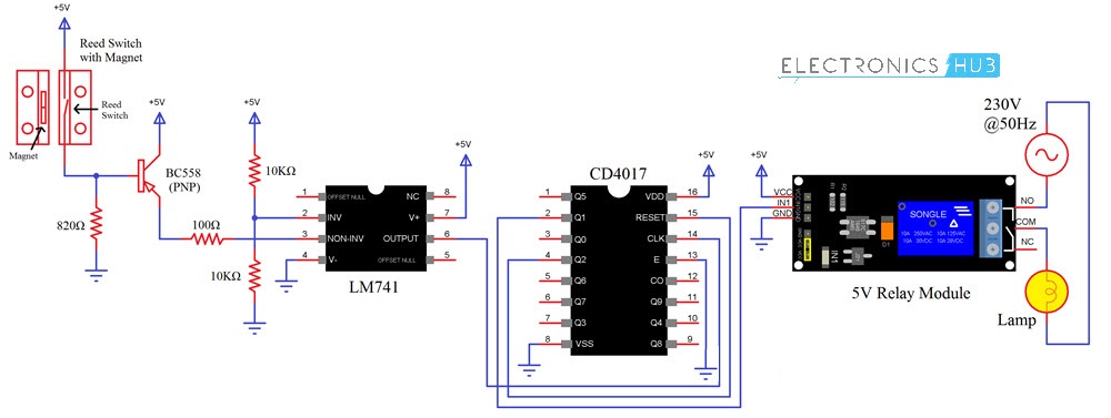
Automatic Washroom Light Switch Circuit Diagram
Components Required
- Reed Switch with Magnet (available as combination)
- LM741 Op-Amp IC
- CD4017 Decade Counter IC
- 5V Relay Module
- Lamp
- BC558 PNP Transistor
- 2 X 10KΩ Resistor
- 100Ω Resistor
- 820Ω Resistor
- Connecting wires
- Mini Breadboard
- 5V Power Supply
A Brief Note on Reed Switch
Reed Switch is one of the important components of this circuit and in fact the element which is used to detect the opening and closing of the door in this project is a reed switch. The following image shows a typical reed switch.
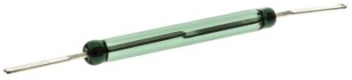
A Reed Switch is a magnetically operated switch. It contains a magnetic sensitive switch, which when subjected to a small magnetic force, will either close or open (depending on its construction).
There are two types of reed switches. One type with Normally Open Contact and the other with Normally Closed Contact.
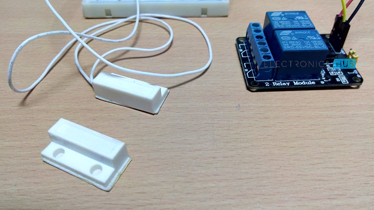
The Reed Switch used in this project is shown below. You cannot see anything as it is placed in a housing but the part with wires is the Reed Switch and the other part consists of a magnet.
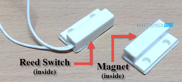
This is a Normally Open NO type switch i.e. usually the switch is open and when a magnet is placed near the switch, it will be closed.
Reed Switches are mainly used in detecting whether door is open or not. It can also be used as a proximity sensor.
Circuit Design
The first important component is the LM741 Op-Amp. It is being operated in comparator mode. Pin 2 is the inverting input of LM741 and its input is given from two 10KΩ Resistors.
One end of the Reed Switch is connected to +5V supply while the other end is connected to base of a PNP Transistor (BC558). Also, the base of the transistor is pulled down with the help of a resistor.
The emitter of the transistor is connected to the Non-inverting input of the Op-Amp while the collector of the transistor is connected to +5V.
Pin 1 of LM741 i.e. its output is connected to the CLK input of CD4017 i.e. its Pin 14. Pin 2 of CD4017 is connected to the input of the relay while Pin 4 is connected to Pin 15.
Rest of the connections can be easily understood from the circuit diagram.
WARNING: If you are planning to use a real light bulb that runs on AC Supply, be extremely careful when connecting it to the relay and providing the mains supply.
Working
Before continuing with the working of the circuit, I will first explain the intended setup of this circuit. The reed switch is fixed to the wall near the door while the magnet is fixed to the door. This means that the reed switch will always be in closed state as the door is closed when the washroom is not in use (which is assumed as starting point) and the magnet will be near the switch.
Assume you opened the door and entered into the washroom and then closed the door behind you. This action will make the switch open (when the door is opened first) and close (when you close the door).
As a result, the output of the Op-amp goes HIGH (when you open the door)and then goes LOW (when you close the door). This in turn will cause the counter to produce a HIGH output at its Pin 2. Since Pin 2 of CD4017 is connected to the relay, the light will be turned ON.
Now, when you are done with your business in the washroom, you will once again open the door, come out of the washroom and close the door. This action will once again cause the same action i.e. switch will open and close and output of Op-Amp will become HIGH and then LOW.
But, since the Pin 4 of CD4017 is connected to the Reset pin, all the outputs will become LOW and hence the relay will be turned OFF, which in turn switches off the light.
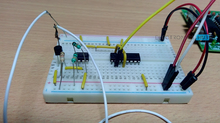
Operation of the Circuit
- Make the connections and power on the circuit.
- Open the door of the washroom, enter the washroom and close the door behind you.
- This action will turn ON the light of the washroom.
- Once you are done, open the door, leave the washroom and close the door.
- This action will turn OFF the light of the washroom.
Read good post on Automatic Door Bell With Object Detection
Read the following posts also:

68 Responses
can u please give me the details of the IC 4017….. Is it a flip flop?
It’s decade counter
Plz you can tell me, why use a decoder counter ic
The counter will count at the speed of the Clock Pulse. When it counts to 10 it will reset to 0. By choosing one of the Outputs, you can control the states before it resets.
It you choose output 1 then you will have two states,
The ON STATE and the OFF STATE. (1, 0)
Is it possible to do this project with a flip flop and IR?
If possible, can you please send me the details in my email id…..?
yes its possible
Tomorrow I go to work on this project
very intresting
yeah
the IC 4017 is used as the counter..
Very interesting, why did not I think of that ..
THANKS
when we are using this automatic switch on and off system in the day time there will be arise watse of power due to automatic switch on system… is there any steps to avoid this problem?
Combine with dimmer circuit
try replacing the voltage divider resistors (2 x 10kΩ) connected across inverting input (pin 2) with LDR and 10kΩ POT.
intresting & its possible
I just finished on the test breadboard, and I can say it works perfectly. Thanks
I am getting problem on doing this on breadboard..can u plz help
I am also getting problem in implementing it .Any help would be greatly appreciated.
can anyone resolve my problem ,there is no respone of reed switch wether magnet is near reed switch or not
is it possible to change the switch into ldr or condenser mic.???
This circuit can be done much more simpler, you dont need ic741 or 4017 only thing you need is switch and relay and 4013 flip-flop 😀
David can you give me the circuit diagram ??
HI BRO , can u pls snd me the connection details.
I arranged the same circuit in practical, but i am not getting result.
What to do please reply me.
I’m a little confused as to how this circuit automates the washroom lights. How do you connect the circuit to the light?
in simple, try to connect the relay in parallel to the electrical switch of the bulb. so that the bulb glows either by a switch (manually) or relay (automatically).
if you are a beginner then we won’t recommend you to work on 230v supply without any supervision of an expert.
why you not use IC 555 as Astable?
i want mini project on Automatic Washroom Light Switch
I hope the above information about Automatic Washroom Light Switch is sufficient to make a mini project on your own. if you are facing any problem regarding building or calibrating the circuit feel free to leave a comment.
Yeah. What is the purpose of Bc558 transistor in this circuit?
What is the suitable component to replaced condenser microphone ?
Does the 9v sources are separated or they can all go to the same source?
If the first case, ¿How many sources do i need?
I want a make a mojar project
Tell me any idea any body
Very intresting , please send detail for this project
I think this project maybe can install in my house.
Can send me in detail for this project?
We have provided all the required data in the project..Please go through the project completely and further if you need any information contact us..
Hi admin lm a student of cagayan state university CSU.i need latest or inovation to my majore i begging pls to help me on my research project
I want to use IR instead of reed switch woth same IC and mechanism. Of possible, Please reply
please im doing a project on automatic washroom light control using LDR i need chapter 3 of that
please provide the working operation and the principle of the project sir as early as you can sir
awaiting your reply
I need a simple and much more better working project than this can you suggest me some m0re with such kind of ideas?
I tried to make this circuit but its not working???
Need help
I have a interest in those things where above given it helps me to know the applicationsof ddifferentccomponents thank you…
I need the explaination of all the resistance used in the circuit of automatic washroom light ;Why it is used at the particular places ?pls help
please give me circuit diagram using relay and 4013 flip-flop
hello Dear:
could i get its simulation ? step on proteus? it is not fuction as circiut is constructed.
Very Good Information Provided Here. Thanks
Two questions:
1. Where do I put in the power supply? Will it be DC? What should be the voltage?
2. I can see two arrow-type components (somewhat like two gates) in the circuit, pointed upwards. What are those?
what can I use as a replacement to LM741 Op-Amp IC?
But it is impractical,as if one person enters washroom and close door,light will also be switched off.
DISADVANTAGE:
But it is impractical,as if one person enters washroom and close door,light will also be switched off.
Thanks for this incredible project.
Can you please send me this project in full to my email?
There are 3 types of relay so which relay is used in this project
could you please be more specific.
can anyone tell me why we use pnp and amplifier plz ? .. and also … my counter doesn’t countin right … can tell me what’s the problem ?
i really enjoy it yeah its working
Can i have wiring diagrams circuit plz
at present, we don’t have any wiring diagram to provide. but the actual connection is pretty simple. all you have to do is to connect the relay (Normally Open (NO) and Common pin) in parallel to the electrical switch of the bulb. thus, the bulb will work either by the switch (manually) or relay (automatically).
WARNING: If you are planning to use a real light bulb that runs on AC Supply, be extremely careful when connecting it to the relay and providing the mains supply.
Very Nice project Absolutely awesome… i have implemented in my washroom. it is working ..but facing two problems.
.1) sometimes relay gets automatically switch on or off without any door movement.
2) there are other switches in my bathroom like exhaust fan, geyser etc. sometimes when i switch on any of these switches relay gets signal & turn the light on/off. (Note:- i have used adopter to give 5 V to circuit & adopter(230 v AC to 5 V DC) is connected to same board where other switches are.
Hello, i have connected everything, the input at pin 3 of 741 is varying with reed switch but no change in the output, yet i have ref voltage at pin 2. Pls assist
– check everything properly grounded or not.
– try to trigger the decade counter ic manually. if it works then, do the same to the op-amp. but if you are facing the same problem again then, change the magnet. if it still continues then replace the op-amp.
– in the worst case, check the power supply. because this circuit designed to work at 5v supply. if the voltage drops then it will affect the reference voltage.
– try to replace the 2 x 10kΩ resistor with 50kΩ pot. it helps you to calibrate the circuit easily.
What’s the function of the transitor above?
inverts the output corresponding to the reed switch
WHY CAN’T WE DIRECTLY CONNECT OUTPUT OF REED SWITCH (IF WE INVERT OUTPUT OF REED SWITCH USING RELAY BETWEEN REED SWITCH AND CD 4017) TO DIRECT CLOCK PIN OF DECADE COUNTER CD 4017 ?? IT WILL REDUCE MANY COMPONENT IN CIRCUIT …..
your question is really thoughtful. but, connecting relays may increase power consumption. so, again you have to come back to any sort of IC’s to do that job. but here the op-amp not only increases the stability of this circuit but also it helps us for future upgrades like connecting LDR to disable in a bright environment.
Could anyone please send me the Proteus simulation of this project (Automatic Washroom Light Switch) as soon as possible.
Have you completed? How was it
can i please get a project of this kind which works out for all lighting system in a school(not only the washrooms)
I am so happy I found your blog and I absolutely love your information about automatic washroom light switch! I liked and it is wonderful to know about so many things that are useful for all of us! Thanks a lot for this amazing blog!!