The main purpose of any microcontroller is to accept input from input devices and accordingly drive the output. Hence, there will be several devices connected to a microcontroller at a time. Also, there are many internal components in a microcontroller like timers, counters etc. that require attention of the processor.
Since all the devices can’t obtain the attention of the processor at all times, the concept of “Interrupts” comes in to picture. An Interrupt, as the name suggests, interrupts the microcontroller from whatever it is doing and draws its attention to perform a special task. The following image depicts the procedure involved in Interrupts.
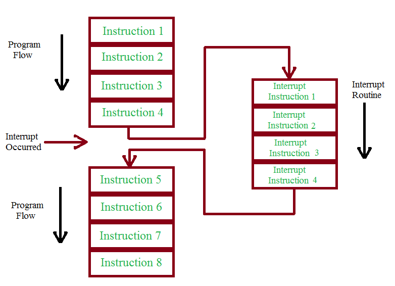
In the event of an interrupt, the source of the interrupt (like a Timer, Counter etc.) sends a special request to the processor called Interrupt Request (IRQ) in order to run a special piece of code. The special code or function is called as Interrupt Service Routine (ISR).
From the above figure, the CPU executes its normal set of codes until an IRQ occurs. When the IRQ signal is received, the CPU stops executing the regular code and starts executing the ISR. Once the execution of the ISR is completed by the CPU, it returns back to execution of the normal code.
Vectored Interrupt Controller (VIC) handles the interrupts in LPC214x series of MCUs. It can take up to 32 Interrupt Requests. The interrupts in LPC2148 microcontroller are categorized as Fast Interrupt Request (FIQ), Vectored Interrupt Request (IRQ) and Non – Vectored Interrupt Request. All the interrupts in LPC214x have a programmable settings i.e. the priorities of the Interrupts can be dynamically set.
Of the three categories, the FIQ requests have the highest priority, Vectored IRQ requests have the medium priority and non – vectored IRQ requests have the least priority.
When we are talking about “Vectored” and “Non – Vectored” IRQ requests, we are actually talking about the address of the ISR. In case of Vectored IRQ requests, the CPU has a knowledge of the ISR. A special table called Interrupt Vector Table (IVT) contains all the information about the Vectored IRQ. This information can be about the source of the interrupts, ISR address of the IRQ requests etc.
So, each Vectored IRQ has its own unique ISR address. Out of the possible 32 interrupt requests, 16 interrupt requests can be defined as Vectored IRQ. In this 16 slots, any of the 22 interrupts that are available in LPC2148 can be assigned. In the 16 Vectored IRQ slots, slot 0 has the highest priority while slot 16 has the least priority.
In case of Non – Vectored IRQ, as the name itself indicates, the CPU isn’t aware of either the source of the Interrupt or the ISR address of the Interrupts. In this case, the CPU must be provided with a default ISR address. For handling Non – Vectored IRQ requests, a special register called “VICDefVectAddr” is available in LPC2148. The address of the default ISR must be given in this register by the user in order to handle the Non – Vectored IRQ requests.
Note: All the Non – Vectored IRQ Requests have the same ISR address which is defined in the VICDefVectAddr register.
Interrupt Related Registers in LPC2148
There are many registers corresponding to Vectored Interrupt Controller (VIC). These registers are used to either configure the interrupts or read the status of the interrupt. The important thing to remember about all the registers related to VIC is that each bit is associated with a particular interrupt source in all the VIC registers. Bit 0 is associated with Interrupt corresponding to Watch dog Timer and it is same in all VIC related registers.
The following table shows the list of 22 interrupt sources in LPC2148 and their corresponding Bit position in VIC registers.
| Bit# | 22 | 21 | 20 | 19 | 18 | 17 | 16 | 15 | 14 | 13 | 12 | 11 |
| IRQ | USB | AD1 | BOD | I2C1 | AD0 | EINT3 | EINT2 | EINT1 | EINT0 | RTC | PLL | SPI1/SSP |
| Bit# | 10 | 9 | 8 | 7 | 6 | 5 | 4 | 3 | 2 | 1 | 0 | |
| IRQ | SPI0 | I2C0 | PWM | UART1 | UART0 | TIMER1 | TIMER0 | ARMCore1 | ARMCore0 | N/A | WDT |
The following is the list and description of registers that are associated with Interrupts in LPC214x series MCUs. The registers mentioned here are few important of the total available VIC Registers and are also in best order to start learning about VIC.
- Software Interrupt Register (VICSoftInt): Software Interrupt Register is used to manually generate the interrupts using software i.e. code before the masking by external source. When a bit is set with 1 in the VICSoftInt register, the corresponding interrupt is triggered even without any external source.
- Software Interrupt Clear Register (VICSoftIntClear): Software Interrupt Clear Register is used to clear the bits set by Software Interrupt Register. When a bit is set to 1 in this register, the corresponding bit in the Software Interrupt Register is cleared and hence releasing the forced interrupt.
- Interrupt Enable Register (VICIntEnable): Interrupt Enable Register is used to enable the interrupts that can later contribute to either FIQ or IRQ. When a bit is set to 1, the corresponding interrupt is enabled. As this is a read / write register, when this register is read, “1” indicates that the external interrupt request or software interrupts are enabled.
- Interrupt Enable Clear Register (VICIntEnClear): Interrupt Enable Clear Register is used to clear the bits set by the Interrupt Enable Clear Register i.e. it is used to disable the interrupts. When a bit is set with “1”, the register allows the software to clear the corresponding bit in the Interrupt Enable Register and thus disabling the interrupt for that particular request.
- Interrupt Select Register (VICIntSelect): Interrupt Select Register is used to classify each of the 32 interrupts as either FIQ or IRQ. When a bit in this register is set to “0”, then the corresponding interrupt (as shown in the above table) will be made as an IRQ. Similarly, when a bit is set to “1”, the corresponding interrupt is made as FIQ.
- IRQ Status Register (VICIRQStatus): Interrupt Status Register is used to read out the status of the interrupts that enabled and declared as IRQ. Both Vectored and Non – Vectored IRQ are read out. When a bit is read as “1”, then the corresponding Interrupt is enabled and defined as IRQ.
- FIQ Status Register (VICFIQStatus): This register is similar to IRQ Status Register (VICIRQStatus) except it reads the status of interrupts that are enabled and defined as FIQ.
- Vector Control Registers (VICVectCntl0 – VICVectCntl15): Vector Control Registers are used to assign slots to different interrupt sources that are classified as IRQ. There are 16 Vector Control Registers and each register controls one of the 16 Vectored IRQ slots. VICVectCntl0 (Slot 0) has the highest priority while VICVectCntl15 (Slot 15) has the least priority. The first 5 bits in the Vector Control Registers (Bit 0 – Bit 4) contains the number of the interrupt request. The 5th bit (Bit 5) is used to enable the Vectored IRQ Slot. The following tables are be used to show the interrupt source and their corresponding Source Number in Decimal format.
| Interrupt Source | Source Number in Decimal |
| WDT | 0 |
| N/A | 1 |
| ARMCore0 | 2 |
| ARMCore1 | 3 |
| TIMER0 | 4 |
| TIMER1 | 5 |
| UART0 | 6 |
| UART1 | 7 |
| PWM | 8 |
| I2C0 | 9 |
| SPI0 | 10 |
| SPI1 | 11 |
| Interrupt Source | Source number In Decimal |
| PLL | 12 |
| RTC | 13 |
| EINT0 | 14 |
| EINT1 | 15 |
| EINT2 | 16 |
| EINT3 | 17 |
| ADC0 | 18 |
| I2C1 | 19 |
| BOD | 20 |
| ADC1 | 21 |
| USB | 22 |
For example, if we want to assign Slot 0 to Timer0 IRQ, then the Vector Control Register must be declared as follows:
VICVectCntl0 = 0x20 | 4;
Note: When a Vectored IRQ is disabled in any of the VICVectCntl0 – 15 registers, it will not disable the actual interrupt but the Vectored IRQ is changed to Non – Vectored IRQ.
- Vector Address Registers (VICVectAddr0 – VICVectAddr15): Vector Address Registers are used to hold the addresses of the ISR of the 16 Vectored IRQ slots. If Slot 0 (VICVectCntl0) is assigned to TIMER0 IRQ, then the address for the interrupt function must be assigned to VICVectAddr0.
- Default Vector Address Register (VICDefVectAddr): Default Vector Address Register holds the address of the ISR for Non – Vectored IRQs. This address acts as the default or common ISR address when a Non – Vectored IRQ occurs.
- Vector Address Register (VICVectAddr): This is a different and single register and must not be confused with Vector Address Registers (VICVectAddr0 – VICVectAddr15). It is a read / write register and when the data is read from this register, it returns address of ISR. Writing a value to this register indicates the VIC that the execution of the current interrupt is finished. Hence, this register is written with a dummy value at the end of the ISR to indicate the end of execution.
Configuring Interrupts in LPC2148
Now that we have seen the list and functionalities of different registers associated with VIC, we will see how to configure interrupts and define the respective ISRs. For that, first we will see how to properly define the ISR function so that the compiler understands that it is an ISR but not a regular function.
In Keil IDE, we can define the ISR in two ways and in both the cases we need to use the keyword “__irq”.
// the first way to define ISR
__irq void userISR (void)
{
/////////
}
// or the following way to define the ISR
Void userISR (void) __irq
{
///////
}
After defining the ISR, now we will setup the interrupt. For example, consider we want to assign TIMER0 IRQ and the corresponding ISR to Slot 0. For this, we need to follow three steps.
- Enable the TIMER0 IRQ (using VICIntEnable Register)
- Allocate Slot 0 to TIMER0 IRQ (using one of the VICVectCntl0 – 15 Registers)
- Assign the ISR Address (using one of the VICVectAddr0 – 15 Registers)
Based on the above steps, the following assignments must be made to setup the interrupt.
VICIntEnable | = (1<<4);
VICVectCntl0 = 0x20 | 4;
VICVectAddr0 = (unsigned) userISR;
Example program using Interrupts in LPC2148
Now, we will see an example program using interrupts in LPC2148 MCU. We will use the Timer to generate a delay and a timer interrupt to blink the LEDs.
#include<lpc214x.h>
#define led 0xFFFFFFFF;
int z=0;
/* Function definition for the timer function */
void timer (void)
{
T0CTCR = 0x00;
T0PR = 60000-1;
T0TCR = 0x02;
T0MR0 = 1000-1;
T0MCR = (1<<0) | (1<<1);
}
/* Function definition for the delay function */
void delay (int d)
{
T0TCR=0x02;
T0TCR=0x01;
while (T0TC < d);
T0TCR=0x00;
}
/* ISR for the Interrupt */
__irq void timerISR (void)
{
long int val;
val = T0IR;
if (z==0)
{
IOSET1 = led;
}
else
{
IOCLR1 = led;
}
z=~z;
T0IR = val;
VICVectAddr = 0x00;
}
/* Function definition for Interrupt Function */
void interrupt (void)
{
VICIntSelect = 0x00;
VICIntEnable |= (1<<4);
VICVectCntl0 = 0x20 | 4;
VICVectAddr0 = (unsigned) timerISR; // Pointer for the ISR
}
int main()
{
PINSEL2 = 0x00;
IODIR1 = led;
/* Enable PLL block and set the CCLK and PCLK to 60 MHz */
PLL0CON = 0x01;
PLL0CFG = 0x24;
PLL0FEED = 0xaa;
PLL0FEED = 0x55;
while (!(PLL0STAT & 0x00000400));
PLL0CON = 0x03;
PLL0FEED = 0xaa;
PLL0FEED = 0x55;
VPBDIV = 0x01;
/* Call the Timer Function */
timer();
/* Call the Interrupt Function */
interrupt();
/* Enable Timer */
T0TCR = 0x01;
while(1);
}

3 Responses
Easy to understand.Thank you
Hi Delay function is not required.
Delay function not called.