

We know the importance of notice boards in public places like railway stations, bus stations and airports. But changing notices day-to-day is a difficult task. This article explains you how to design a Wireless Electronic Notice Board using GSM technology. The project displays the data on LCD whatever we sent from the mobile.
There are many wireless communication technologies like Bluetooth, RF Communication, ZigBee, etc. but GSM Technology based communication allows long range, reliable and secure communication.
Wireless Electronic Notice Board using GSM
The Wireless Electronic Notice Board using GSM project, as the name suggests, is built around GSM Technology as mobile phones (that communicate through GSM Technology) have become very abundant, cheap and easy to use.
NOTE: We need a Mobile Phone to send the Message (Notice) and a GSM MODEM to receive that notice.
Related Post: RFID Based Attendance System using Microcontroller
Construction and Output Video
Circuit Principle
When we send the message from the mobile, the GSM Modem which is connected to the Microcontroller and the display unit, will receive the message. Now, the microcontroller reads the message from the GSM Modem and displays it on LCD.
When user sends the message from the mobile, GSM modem sends the below command serially to indicate that a new message is received.
+CMTI: “SM”,3
In the above command, number “3” indicates the location of the new message i.e. it is the third message in the inbox. Now you need to read this unread message to display on LCD. The command to read the message from GSM modem is
AT+CMGR=3
Here, the number “3” indicates the location of the message to be read. After giving this command to the GSM module, it will send the below command serially.
+CMGR: “REC UNREAD”,”MD-WAYSMS”,,”13/05/20,15:31:48+34″
Electronics Hub
In the above command, “REC UNREAD” indicates that message is unread message, “MD-WAYSMS” indicates sender mobile number or name, 13/05/20 indicates the date, 15:31 indicates time and Electronics hub is the content of the message.
From the above command we need to extract message (Electronics Hub) sent by the user to display it on the notice board (LCD).
Circuit Diagram of Wireless Electronic Notice Board using GSM
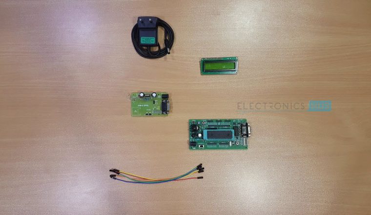
Components for Wireless Electronic Notice Board using GSM
Hardware Requirements
- 8051 Microcontroller (AT89C51)
- 8051 Programming board (Programmer with cable)
- 8051 Development Board
- SIM 900A GSM MODEM (GSM Module)
- SIM Card (for inserting in GSM Modem)
- A mobile phone with a SIM Card already inserted
- 16 x 2 LCD Display
- 10 KΩ Potentiometer
- Connecting wires
- Power Supply
- If 8051 Development Board is not available, then you need the following components
- 2 x 10 KΩ Resistors (1/4 Watt)
- 2 x 33pF Ceramic Disc type Capacitors
- Push Button
- 10µF / 16V Capacitor (Polarized)
- 0592 MHz Quartz Crystal
Software Requirements
- Keil µVision IDE (for writing the program and generating .hex file)
- Willar Software (for burning the .hex file in to the microcontroller)
- Proteus (for circuit diagram and simulation)
Circuit Design
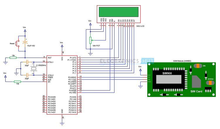
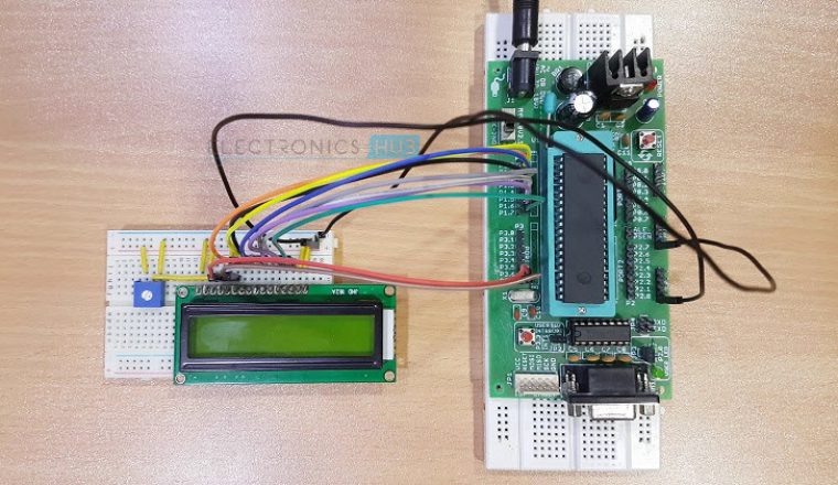
The above circuit of the Wireless Electronic Notice Board using GSM consists of 8051 Microcontroller, GSM Module (Modem) and 16 x 2 LCD. Here, the 16 x 2 LCD is used to display message and is used in 8 – bit mode. Means, we need 8 data lines to display the data. The data lines of the LCD Display are connected to PORT1 Pins. The control pins RS, RW, and E pins are connected to P3.6, GND and P3.7 pins respectively.
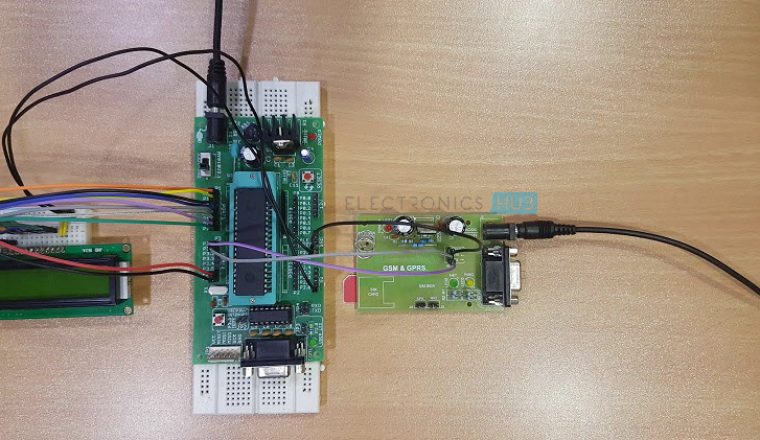
The GSM Module is directly connected to the microcontroller as the logic levels of both the GSM Modem and Microcontroller are already matched in the GSM Module Board. If there is no level converter on the board, then we need to use MAX232 level converter as a mediator between Controller and GSM to transfer the data.
To know more details about max232 refer Max232 Datasheet
In order to communicate with the GSM Modem, we need to send some AT commands using serial communication (UART protocol). Here, GSM SIM 900A module is used. This module requires 9600 baud rate.
To know more details about GSM go through the article GSM Interfacing with 8051 Microcontroller
Circuit Algorithm
- Initialize the LCD and UART protocol
- Check for the command +CMTI: “SM”,3 (Location number) to know whether the new message is received or not.
- If you receive the command, then store message location number.
- Now read that particular location and extract the body of the message.
- Display the message on LCD.
Use below code to display message on LCD wirelessly using GSM
while (rx_data() ! = 0x0d);
while (rx_data() ! = 0x0a);
if (rx_data() == ‘+’)
{
if (rx_data() == ‘C’)
{
if (rx_data() == ‘M’)
{
if (rx_data() == ‘T’)
{
if(rx_data()==’I’)
{
while (rx_data() != ‘,’);
a = rx_data ();
delay_ms (10);
tx_string (“at”);
tx_data (0x0d);
tx_data (0x0a);
tx_string (“at + cmgf =1”);
tx_data (0x0d);
tx_data (0x0a);
tx_string (“at + cmgr =”);
tx_data (a);
tx_data (0x0d);
tx_data (0x0a);
while (rx_data() ! = 0x0a);
while (rx_data() != 0x0a);
while (rx_data() ! = 0x0a);
for (i=0; i<15; i++)
{
read [i]= rx_data();
}
lcd_stringxy(1,0,read);
delay_ms (5000);
}
}
}
}
}
Circuit Simulation Video
How to Operate Wireless Electronic Notice Board using GSM?
- Write the program to the wireless electronic notice board using Keil software
- Now burn the program to the microcontroller with the help of hardware programmer and Willar Software.
- Give the connections as per the circuit diagram.
- Use power supply circuit to provide 5V DC to the microcontroller
- Insert the SIM (Subscriber Identity Module) to the GSM module.
- Now switch on the supply
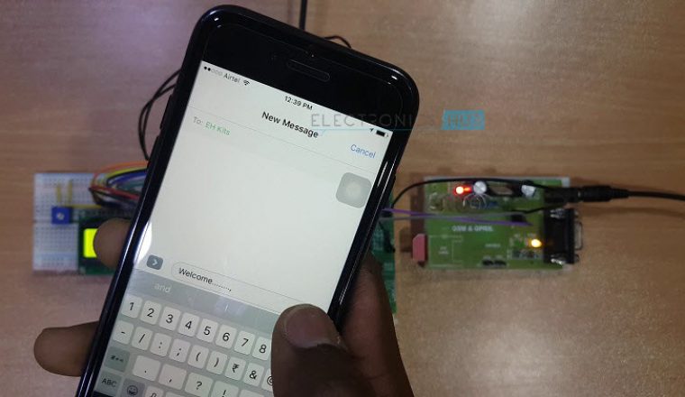
- Send SMS to the GSM module using other mobile
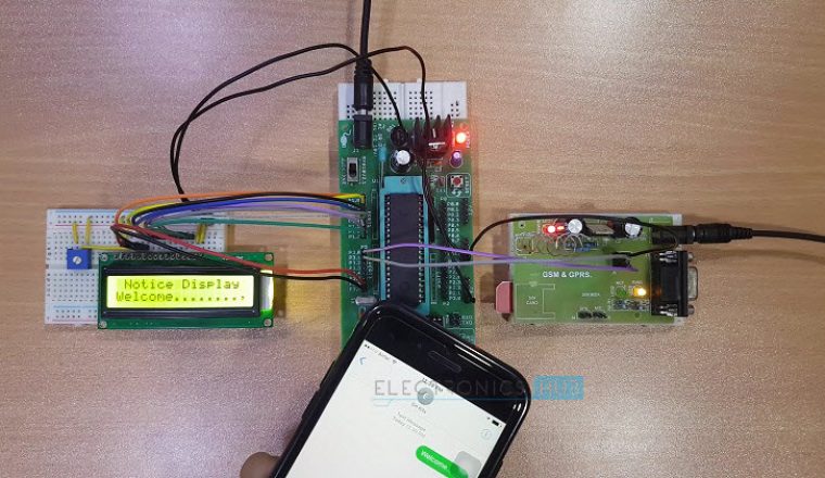
- Now you can see the same message on LCD.
Circuit Advantages
- No need of any complex wires to display the message on LCD as it is wireless.
- Consumes less power and easy to operate.
- The circuit is portable.
Circuit Applications
- Used in bus stations, railway stations, parks, etc. to display the messages wirelessly
- This Project can also be used in colleges and organizations.
Circuit Limitations
- Display unit must have the network to receive the message wirelessly
- As there is no password any one can send the message to display.
Download Project Code
128 Responses
Hi;Thank you for what you ‘ve
I wanted to take up orders please email me the AT commands interfacing module sim300 with the microcontroller ‘s AT89C51
I urgently need my urgent orders , please
1.Why you need this project code?
Ans:I am student of BSMRSTU, I am in EEE branch. i am doing my final year project with the same topic as above. i want this code to understand the serial interface of at89c52 and gsm using functions and c codes.
2.re you trying to make the same project or different one?
Ans: My project is almost same to it.
3.Give us more details about your project.
Ans: My project is wirless Electronic notice board by GSM and shown pdf in screen by using GSM communication.
If you want to use it in colleges, notices are big size( more number of characters), then what we have do now???
My friend has recently done this project using the circuit shown in this post. It is working fine. Thanks for sharing.
Hi, i really interested with this project.can you please share the code..saifulamer9110@gmail.com
Really appreciate..
I want to do this project. I humbly request you to please send me the code
Why you need this project code?
Ans- i am a student of juet guna, doing b tech from ECE branch, i am doing my final year project with the same topic i.e. “gsm based e-notice board”. we are done with microcontroller and lcd interfacing, but now for the other segment of the project i.e. gsm and controller interface we are facing some problem. the problem is we are using the same software keil for compilation, here we do not have any idea about the functions and header files to be used for AT89C52 and GSM serial communication, we want to send AT commands to gsm using AT89C52 and how microcontroller will respond to this. so all functions required to perform the task we need, so if you will send your complete project code(including header files and functions definitions) to me, i will be able to sort out my problems regarding coding.
we are in urgent need so please respond as soon as possible.
Are you trying to make the same project or different one?
Ans- yes the project is almost same.
Give us more details about your project.
Ans- in our project we want to transmit the msg recieved by gsm module to lcd display with some other modifications like gsm to mobile acknowledgement, network detection by microcontroller etc.
Please can you send me the project code.I am doing this project in my college. I need urgently, can u forward this code to my mail , my mail id is gaya3404@gmail.com
i am mtech student so i need that code
Can you please send me the code I am doing the same project
Code is there in the article, thanks
But complete code is not there
simulation is done in which software…………..and can it be done for lpc2148 microcontroller….please reply fast
Will u plz send me full code of wireless electronic notice board
Why you need this project code?
Ans- i am student of juet guna, doing btech from ECE branch. i am doing my final year project with the same topic as above. i want your project code to understand the serial interface of at89c52 and gsm using functions and c codes.
Are you trying to make the same project or different one?
Ans- the project is almost same.
Give us more details about your project.
Ans- it is our final year project. i will be very thankful to you if i get your project code because i am in urgency. please help
thankyou so much
Please can you give me the code in assmebly language for ATNEGA32 or for 8051. I need it ASAP. Yes i am doing the same project in my college,
i am very interested to do this project, can you please provide me the codes.