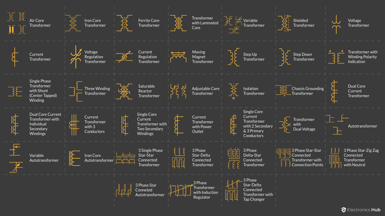
A Transformer is an important device in modern electrical power systems. There are large power transformers in power plants, substations, distribution poles and relatively small transformers in our electronic appliances. Irrespective of the size and location, all transformers work on the same principle. There are different types of transformers that are designed for specific set of applications. To represent all these transformers in schematics or drawings, we make use of respective Transformer Symbols. A Transformer Symbol is a diagrammatic/pictorial representation of transformers.
In this guide, let us briefly understand about transformers, see the different types of transformers and also tabulate all Transformer Symbols with a simple explanation.
Outline
ToggleIntroduction to Transformers
The Transformer is a static equipment that works on the principle of Faraday’s Law of Electromagnetic Induction. A simple transformer consists of just two conducting coils. The energy in one coil is transferred to another coil through magnetic field (mutual induction).
Transformer with just two coils floating in air is not that effective in transferring energy. Hence, a transformer consists of a magnetic core built using laminated steel. Coil is wound on this core. The winding that receives electric power is known as Primary Winding and the coil that delivers power to a load is known as Secondary Winding.
According to Faraday’s Law, when we supply an alternating voltage to the primary winding, it generates an alternating magnetic flux in the core. This flux will then induce an EMF in the secondary winding. If we connect a load to the secondary winding, then an electric current flows through it due to the emf.
Hence, energy from the primary coil is transferred magnetically to the second coil, without any direct contact between the two coils. So, we use transformers in several electric power systems to transfer power between two circuits working at same frequency by means of electromagnetic induction with varying voltage and current values.
Speaking of voltage and current, depending on the number of windings in primary and secondary coils, the voltage will either decrease or increase from primary to secondary (with a corresponding increase or decrease in current).
Different Types of Transformers
Depending on the application, the style, type and construction of a transformer changes. Let us now see different types of transformers.
- Air Core Transformer
- Iron Core Transformer
- Step Up Transformer
- Step Down Transformer
- Single Phase Transformer
- Three Phase Transformer
- Isolation Transformer
- Autotransformer
- Air Core Transformer: It is one of the simplest types of transformers. An air transformer consists of two coils separated by air. Due to its inefficient performance, we use air core transformers only in small power applications.
- Iron Core Transformer: In an Iron Core Transformer, there is a steel core (or any magnetic core) with coils around it. The ability to carry magnetic flux is known as Permeability and Iron or Steel have very high permeability. Most power transformers use windings on laminated steel core.
- Step Up Transformer: A step up transformer has higher number of secondary windings than primary windings. As a result, the secondary voltage is greater than the primary voltage. We use these transformers to increase the voltage at power plants to several thousand for long distance transmission.
- Step Down Transformer: The opposite of step-up transformer is step down transformer. Here, the secondary windings are less than primary windings and hence, the secondary voltage is less than primary voltage. Distribution transformers that we see in our streets are step down transformers. They reduce primary voltage in kilovolts to 110V or 230V depending on where you live.
- Single Phase Transformer: In a Single-Phase Transformer, both the primary and secondary voltages are single phase AC. Before the development and popularity of switching power supplies, many AC to DC power supplies are linear power supplies that relied up on single phase transformers (step down).
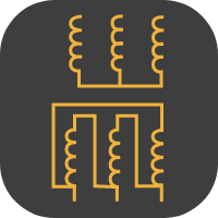
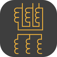
- Three Phase Transformer: Most of the electric power generated in usually three phase. For transmission and distribution of this power, we need three phase transformers. In a three-phase transformer, the core has three legs with three primary windings and three secondary windings. Further three phase transformers have multiple types depending on how we connect the primary and secondary windings (Star – Delta, Delta – Star, Star – Star, Delta – Delta, etc.).
- Isolation Transformer: The main job of an isolation transformer is to provide galvanic isolation between the primary and secondary circuits. Usually, the turns ratio of primary to secondary is 1 but you can have step up or step-down configurations as well.
- Autotransformer: An autotransformer is a special type of transformer that has only one winding for both primary and secondary. It makes use of taps to differentiate between primary and secondary connections.
Transformer Symbols
Transformer Symbols Chart
    | |
 | |
 | |
 | |
   | |
 | |
 | |
 | |
 | |
 | |
 | |
 | |
 | |
 | |
 | |
 | |
 | |
  | |
 | |
 | |
 | |
 | |
 | |
 | |
 | |
 | |
 | |
   | |
  | |
 | |
 | |
 | |
 | |
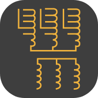 | |
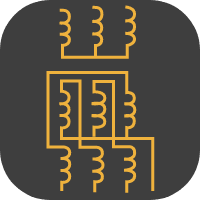 | |
 | |
 | |
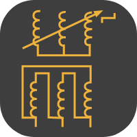 | |
Single Line Transformer Symbols
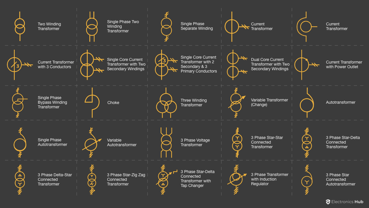
Let us now see the single line transformer symbols. The following image shows all the popular single line transformer symbols in a group. Later, we have individual symbols.
 | |
 | |
 | |
  | |
 | |
 | |
 | |
 | |
 | |
 | |
 | |
 | |
 | |
 | |
 | |
 | |
 | |
 | |
 | |
 | |
 | |
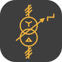 | |
 | |
 | |
Conclusion
Transformers are large devices and if you are working with them, then having a knowledge about different Transformer Symbols will be very handy. In this guide, we saw a brief overview about Transformers, different types of transformers, symbols of transformers and also single line transformer symbols.

