Three phase transformers are more economical for supplying large loads and large power distribution. Even though most of the utilization equipments are connected by the single phase transformers, these are not preferred for large power distribution in the aspect of economy.
The three phase power is used in almost all fields of electrical power system such as power generation, transmission and distribution sectors, also all the industrial sectors are supplied or connected with three phase system. Therefore, to step-up (or increase) or step-down (or decrease) the voltages in the three phase systems, three phase transformers are used. As compared with the single phase transformer, there are numerous advantages with 3 phase transformer such as smaller and lighter to construct for the same power handling capacity, better operating characteristics, etc.

What Is Three Phase Transformer
Three phase transformers are used to step-up or step-down the high voltages in various stages of power transmission system. The power generated at various generating stations is in three phase nature and the voltages are in the range of 13.2KV or 22KV. In order to reduce the power loss to the distribution end, the power is transmitted at somewhat higher voltages like 132 or 400KV. Hence, for transmission of the power at higher voltages, three phase step-up transformer is used to increase the voltage. Also at the end of the transmission or distribution, these high voltages are step-down to levels of 6600, 400, 230 volts, etc. For this, a three phase step down transformer is used.
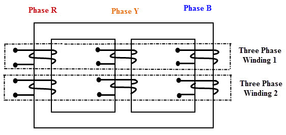
A three phase transformer can be built in two ways; a bank of three single phase transformers or single unit of three phase transformer.
The former one is built by suitably connecting three single phase transformers having same ratings and operating characteristics. In this case if the fault occurs in any one of the transformers, the system still retained at reduced capacity by other two transformers with open delta connection. Hence, continuity of the supply is maintained by this type of connection. These are used in mines because easier to transport individual single phase transformers.
Instead of using three single phase transformers, a three phase bank can be constructed with a single three phase transformer consisting of six windings on a common multi-legged core. Due to this single unit, weight as well as the cost is reduced as compared to three units of the same rating and also windings, the amount of iron in the core and insulation materials are saved. Space required to install a single unit is less compared with three unit bank. But the only disadvantage with single unit three phase transformer is if the fault occurs in any one of the phase, then entire unit must be removed from the service.
Construction of Three Phase Transformers
A three phase transformer can be constructed by using common magnetic core for both primary and secondary windings. As we discussed in the case of single phase transformers, construction can be core type or shell type. So for a bank of three phase core type transformer, three core type single phase transformers are combined. Similarly, a bank of three phase shell type transformer is get by properly combining three shell type single phase transformers. In a shell type transformer, EI laminated core surrounds the coils whereas in core type coil surrounds the core.
Core Type Construction
In core type three phase transformer, core is made up of three limbs or legs and two yokes. The magnetic path is formed between these yokes and limbs. On each limb both primary and secondary windings are wounded concentrically. Circular cylindrical coils are used as the windings for this type of transformer. The primary and secondary windings of one phase are wounded on one leg. Under balanced condition, the magnetic flux in each phase of the leg adds up to zero. Therefore, under normal conditions, no return leg is needed. But in case of unbalanced loads, high circulating current flows and hence it may be best to use three single phase transformers.
Shell Type Construction
In shell type, three phases are more independent because each phase has independent magnetic circuit compared with core type transformer. The construction is similar to the single phase shell type transformer built on top of another. The magnetic circuits of this type of transformer are in parallel. Due to this, the saturation effects in common magnetic paths are neglected. However, shell type constructed transformers are rarely used in practice.
Working of Three Phase Transformers
Consider the below figure in which the primary of the transformer is connected in star fashion on the cores. For simplicity, only primary winding is shown in the figure which is connected across the three phase AC supply. The three cores are arranged at an angle of 120 degrees to each other. The empty leg of each core is combined in such that they form center leg as shown in figure.
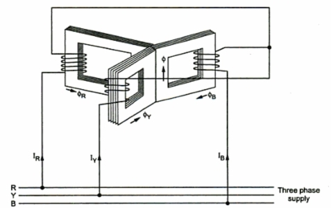
When the primary is excited with the three phase supply source, the currents IR, IY and IB are starts flowing through individual phase windings. These currents produce the magnetic fluxes ΦR, ΦY and ΦB in the respective cores. Since the center leg is common for all the cores, the sum of all three fluxes are carried by it. In three phase system, at any instant the vector sum of all the currents is zero. In turn, at the instant the sum of all the fluxes is same. Hence, the center leg doesn’t carry any flux at any instant. So even if the center leg is removed it makes no difference in other conditions of the transformer.
Likewise, in three phase system where any two conductors acts as return for the current in third conductor, any two legs acts as a return path of the flux for the third leg if the center leg is removed in case of three phase transformer. Therefore, while designing the three phase transformer, this principle is used.
These fluxes induce the secondary EMFs in respective phase such that they maintain their phase angle between them. These EMFs drives the currents in the secondary and hence to the load. Depends on the type of connection used and number of turns on each phase, the voltage induced will be varied for obtaining step-up or step-down of voltages.
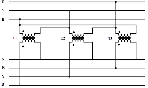
Three Phase Transformer Connections
As discussed above, either by a single three phase transformer or by three single phase transformers combination, three phase transformations can be carried out. The way of connecting the windings for three phase transformation is same whether the three windings of a three phase transformer or three windings of three single phase transformers are used. The primary and secondary windings are connected in different ways, such as in delta or star or combination of these two. The voltage and current ratings of the three phase transformer is depends on suitable connection. The most commonly used connections are
- Star-delta
- Delta-star
- Delta-delta
- Star-star
Star – Delta Connection
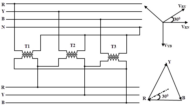
This type of connection is commonly used to step-down the voltages to a lower value in transmission end substations. Utility companies use this connection to reduce the voltage levels for distribution systems.
- In this, the primary winding of the transformer is connected in star and secondary in delta connection.
- The neutral point on the primary or high voltage side can be grounded which is desirable in most of the cases.
- The line voltage ratio between secondary and primary is 1/√3 times the transformation ratio of each transformer.
- There exists 30 degrees phase difference between primary and secondary line voltages.
- Since the actual primary coil voltage is 58% of the primary line voltage, the insulation requirements for HV windings is reduced by using this winding.
- In this connection balanced three phase voltage are obtained at the secondary or LV side, even when the unbalanced currents are flowing the in the primary or HV side due to neutral wire. The neutral wire grounding also provides lightning surge protection.
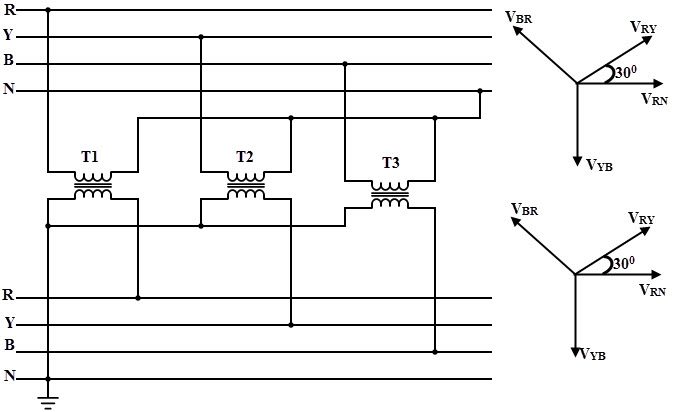
Delta – Star Connection

- This connection is used to step-up the voltage level and is commonly employed in sending end or starting of high tension transmission system.
- In this, the primary is connected in delta fashion and secondary in star fashion so that three phase 4 wire system at secondary is possible.
- The secondary voltage to the load is √3 times the delta connected primary voltage. Also the load and secondary currents will be the same due to the same series circuit.
- This connection provides three single phase circuits at both lower and higher voltages and one three phase circuit at higher voltage so that single and three phase loads can be supplied.
- Dual voltages are obtained delta-star connection. Low single phase voltages are obtained by wiring between any phase and ground. Higher single phase voltages are obtained by wiring between any two phases. And by connecting all three phases to the load, three phase voltage is obtained.
- The insulation requirement on high voltage side is lowered due to the star (less number of turns per phase) connected secondary.
- Similar to star-delta, this connection causes to create a 30 degrees phase difference between primary and secondary line voltages.
- By using this connection, it is not possible to connect it parallel with delta-delta and star-star transformers due to the primary and secondary voltage phase difference.
Delta-delta
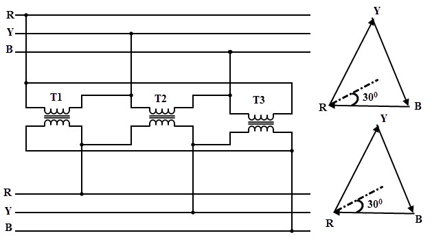
- This type of connection is used when the supply source is delta connected and the secondary load needs single voltage with high current. This is generally employed for three phase power loads (like three phase motor).
- In this, both primary and secondary windings are connected in delta fashion.
- The voltage across the load is equal to the secondary voltage and voltage across the primary winding is equal to source voltage. In this, the current flow through the load will be 1.732 times the secondary current and the feeder current will equal to the 1.732 times current through the primary winding. Due to these high supply and load currents, it is recommended to place transformer much closer to both source and load circuits.
- In this, there exists no phase difference between the primary and secondary voltages.
- The three phase voltages remains constant even with unbalanced load, thus allows unbalanced loading.
- The main advantage of this connection is if the one transformer is defective or removed for service (open delta connection), then remaining two transformers continue to deliver thee phase power at reduced load capacity.
Star – Star Connection
- In this, both primary and secondary windings are connected in star fashion and also there exist no phase difference between the primary and secondary voltages.
- In this, current flowing through both primary and secondary windings are equal to the currents of the lines to which they are connected (supply source and load). And voltages between line phases on either end equal to 1.732 times respective winding voltages.
- Due to neutral availability, it is well suited for three phase four wire system.
- This type connection satisfactorily works if the load is balanced. But if the load is unbalanced, the neutral point shift causes unequal phase voltages.
- Large third harmonic voltages would appear in both primary and secondary windings without the neutral tie. This may lead to the insulation failures.
- This connection considerably generates interference with communication lines and hence with this connection configuration, telephone lines cannot be run in parallel.
- Due to these disadvantages, the star-star connection is rarely used and not employed in practice.
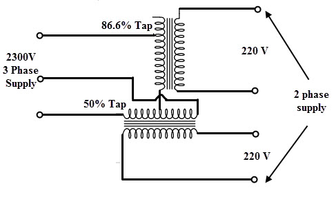
Scott Connection
- This connection is used to convert the three phase power into two phase power using two single phase transformers.
- One transformer called as main transformer having center or 50 percent tap and is connected between the two lines of the three phase wires. The other transformer called as teaser transformer having 86.6 tap and is connected between the third phase wire and 50 percent tap of the main transformer.
- The secondary winding of each transformer provides the phases of two phase systems.
- The secondary voltages in the two transformers will be equal in magnitude if both transformers are wound for equal number of turns on secondary. And produced voltages are 90 degrees out of phase with each other.
- This connection is mainly used to supply the power to the two phase motor.
Advantages of Three Phase Transformers
- Being prewired and ready to install, these can be easier to install.
- To provide the same KVA, the core material required is very less compared to a bank of three single phase transformers.
- It is lighter and smaller.
- It requires less space to install.
- Higher efficiency
- Low cost compared with three units of single phase transformers.
- Transportation is easy and also transportation cost is less.
- Bus bar structure and switchgear installation for single three phase unit is simpler.
- Only three terminals are required to be brought out in case of a three phase transformer compared to six terminals from three single phase transformers.
Disadvantages of Three Phase Transformers
In case of fault or loss of one phase results to the complete unit shut down. This is because in three phase transformer, a common core is shared for all three units. If one unit is defective, the core of this defective unit would immediately saturate because the absence of an opposing magnetic field. This causes the greater escape of magnetic flux to the metal enclosures from the core. This further raises the heating of the metallic parts and in some cases this heat would enough to cause to fires. Therefore, a three phase transformer (or entire unit) must be shut down if any one phase is defective.
- Cost of repair is more for three phase transformer.
- To restore the service, spare unit cost is more compared with one single transformer spare unit.
- When these are self cooled, the capacity of the transformer is reduced.

2 Responses
How to get that colour on the coil ?
Thanks For Providing This Information