A Transformer is a static apparatus, with no moving parts, which transforms electrical power from one circuit to another with changes in voltage and current and no change in frequency. There are two types of transformers classified by their function: Step up Transformer and Step down Transformer.
Step Down Transformer
A Step up Transformer is a device which converts the low primary voltage to a high secondary voltage i.e. it steps up the input voltage. A Step down Transformer on the other hand, steps down the input voltage i.e. the secondary voltage is less than the primary voltage.
The following images shows a simple demonstration of the use of Transformers (both Step up and Step down Transformers) in a typical Transmission System.

Real Time Application of Step Down Transformer
The voltage from the Power Plant or Generation Station is around 20kV. In order to transmit this voltage over long distances, it is stepped up to 440kV using a Step up Transformer. This voltage with increased levels is then transmitted to a distribution station.
At the distribution station, the 440kV is reduced to 11kV using a Step down Transformer. The voltage with decreased level is then made ready for consumer use.
Before going in to the details of the Step down Transformer, we will first see the working principle of a transformer in general.
Also read Introduction to Transformers
Principle of Working of a Transformer
An electrical transformer works on the principle of Mutual Induction, which states that a uniform change in current in a coil will induce an E.M.F in the other coil which is inductively coupled to the first coil.
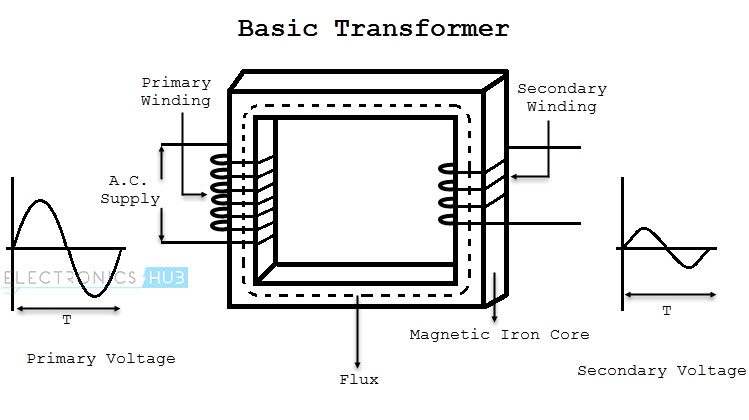
In its basic form, a transformer consists of two coils with high mutual inductance that are electrically separated but have common magnetic circuit. The following image shows the basic construction of a Transformer.
How Transformer Works?
The first set of the coil, which is called as the Primary Coil or Primary Winding, is connected to an alternating voltage source called Primary Voltage.
The other coil, which is called as Secondary Coil or Secondary Winding, is connected to the load and the load draws the resulting alternating voltage (stepped up or stepped down voltage).
The alternating voltage at the input excites the Primary Winding, an alternating current circulates the winding. The alternating current will result in an alternating magnetic flux, which passes through the iron magnetic core and completes its path.
Since the secondary winding is also linked to the alternating magnetic flux, according to Faraday’s Law, an E.M.F is induced in the secondary winding. The strength of the voltage at the secondary winding is dependent on the number of windings through which the flux gets passed through.
Thus, without making an electrical contact, the alternating voltage in the primary winding is transferred to the secondary winding.
Relation Between Voltage and Turns
Let NP be the number of turns of the coil in the Primary Winding and NS be the number of turns of the coil in the Secondary Winding.
If the alternating voltage at the primary side of the transformer is VP and the alternating voltage at the secondary side of the transformer is VS, then the relation between the voltages at primary and secondary and number of turns of the coil in primary and secondary is given as follows.
VP/VS = NP/NS
Step Down Transformer
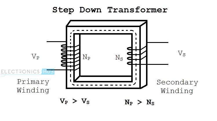
A Step down Transformer is a type of transformer, which converts a high voltage at the primary side to a low voltage at the secondary side.
If we speak in terms of the coil windings, the primary winding of a Step down Transformer has more turns than the secondary winding. The following image shows a typical step down transformer.
Example of Step Down Transformer
For example, consider the following situation. The number of turns in the primary winding of a transformer is 3000 and that in the secondary winding is 150. If the alternating voltage at the primary of the transformer is 240V, then the voltage at the secondary of the transformer can be calculated using the following equation.
VP/VS = NP/NS
Here, NP is primary winding turns = 30000
NS is secondary winding turns = 150
VP is voltage at the primary winding of the transformer = 240V
VS is the voltage at the secondary of the transformer =?
Using the above equation, VS = (VP * NS)/NP = 240*150/3000 = 12V
Hence, the voltage at the secondary winding of the transformer is 12V, which is less than that at the primary. Therefore, the transformer in this subject is a Step down Transformer.
Read this intereseting post on TYPES OF TRANSFORMERS
Power in Step down Transformer
The power in a transformer is measured using the product of voltage and current. The power in a transformer is rated in Volt – Amps VA (or Kilo Volt – Amps kVA for larger transformers).
Ideally, the power in any transformer is constant i.e. the power available at the secondary of the transformer is same as the power at the primary of the transformer.
This is even applicable to a step down transformer. But, since the voltage at the secondary of a step down transformer is lesser than that at the primary, the current at the secondary will be increased in order to balance the total power in the transformer.
Current and Voltage Relation in Step Down Transformer
We will now see how this works. Let VP be the voltage at the primary, IP be the current at the primary and PP be the power at the primary side of the transformer.
We know that the power can be calculated by simply multiplying the voltage and current. Hence, the power at the primary side of the transformer is given by
PP = VP * IP
Similarly, let VS be the voltage at the secondary, IS be the current at the secondary and PS be the power at the secondary side of the transformer.
The power at the secondary of the transformer is given by
PS = VS * IS
Since, the power in a transformer is constant, PP = PS.
Which means, VP * IP = VS * IS
As VS is less than VP in a step down transformer, IS has to be more than IP. Hence, the output voltage in a step down transformer is less than that of the primary voltage and the output current is more than the input current.
From the above analysis, we can define a Step down transformer as a device which converts a High Voltage and Low Current alternating source to a Low Voltage and High Current alternating supply.
Where Step down Transformer is used?
- All the street transformers which we see near our homes are step down transformers. They take a 11kV alternating voltage at the primary and convert it to 230V for distributing it to our homes.
- Before the wide usage of switching power supplies, almost all low voltage wall adapters use step down transformers.

18 Responses
I like this.. this is very informative and authentic infirmation.. ?
vry nice .it helped me a lot
That’s gud job
Very resourceful, i like it!
Very useful, Liked it
Very simple method of the winding coluculat thank you
very nice information, well explained
it clear my confuting information’s..,nice one.thanks
It is very useful for electrical engr I got some knowledge by this
hi, i need to know how to detect the lightning voltages and use these voltage at home
and what transformers to be used and their resistors. plz it’s urgent and i need answers
if possible connect me with professors
can i use these stepdown transformer to convert AC to DC, please give the answer for me
Yes. First Step-down 230V AC to 24V AC or 12V AC, supply it to a bridge rectifier, filter the output of the bridge rectifier and if necessary, use a voltage regulator IC.
what if I use a diode instead of a voltage regulator ic
DIODE IS JUST MEANT FOR REVERSE PROTECTION.IT WONT ALOOW THE CURRENT TO FLOW IN REVERSE DIRECTION .VOLTAGE REGULTER JUST STEP UP OR STEP DOWN THE VOLTAGE ACCORDING TO OUR NEED.
Hey Ravi You stated “Here, NP is primary winding turns = 30000” should be 3000
very interesting information
Nice idea, I really appreciate your tutorial
I love this write up