Almost all AC protective relays in various protection systems are actuated by the current supplied by the current transformers. It is not an easy way to measure the high magnitude alternating current with low range ammeters. And also relays must be rated at high currents to actuate under these high alternating currents. Therefore, the current transformer does the current conversion from high currents to a measurable range of currents. The specific application of current transformers involves in various considerations such as type of mechanical construction, ratio of primary to secondary currents, type of insulation (oil or dry type), thermal conditions, accuracy, service type, etc.
Current Transformers (CTs)
It is a type of current transducer that will give current in the secondary which is proportional in magnitude to the current flowing through the primary. These are used to convert the high currents from power circuit into a measurable current range of instruments and control devices. In addition, they provide isolation to the ammeters, other measuring instruments and control devices from high voltage power circuitry. It is the cheapest and easiest method of current measurement above the range of digital meters and moving coil vane meters.
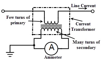
The primary winding of the current transformer consists of one or more turns having a heavy cross sectional area and is connected in series with the circuit in which the current flow is to be sensed. In bar type CTs, the primary winding has only one turn that means the conductor itself acts as primary winding. The secondary winding made with large number of turns of a fine wire having small cross sectional area. This winding is connected to either operating coil of the relay or current coil of the instruments as shown in figure. Very often CTs are designed such that the secondary terminals deliver either 5A or 1A current at full or rated primary current.
Working Principle of Current Transformers
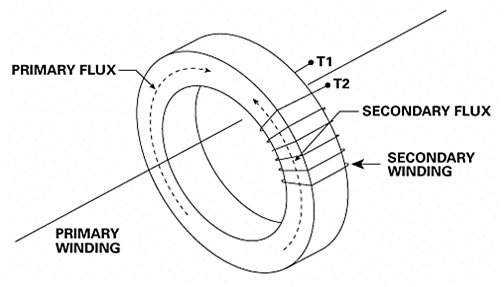
The operation of current transformer is similar to the conventional power transformer. CTs are basically step-up voltage transformers, on the other hand, these are step-down transformers in view of current. This is because at the high voltage side lower will be the current and at low voltage side the current is higher. When primary of the CT is energized, the primary side ampere turns produces a magnetic field in the core. This magnetic flux linking with secondary induces an EMF and this EMF drives the current in the CT secondary. The current in the secondary tries to balance the primary ampere turns. Hence, the relation between the primary and secondary is given as
I1N1 = I2N2
I1 / I2 = N2 / N1
I1/I2 = n
This is called as transformation ratio of the current transformer.
Where I1 and I2 are the primary current and secondary current respectively
N1 and N2 are the primary turns and secondary turns respectively and
n is the turns ratio between secondary to primary winding.
As an example, a typical 100 to 5A current transformer has a nominal ratio of single primary turn to 20 secondary turns or 1:20. From the above equation, by knowing secondary ammeter current and current ratios, we can easily determine the current flowing through the primary which is connected to the main line. In power transformer the primary current is depends on the secondary current. In contrast, the primary winding of the CT is connected directly in series with power circuit and also voltage drop across it is very less and hence the primary current is independent of secondary current.
It should be noted that the secondary of the CT should not be kept open while the primary is energized. If the secondary is left open, the secondary current becomes zero, but practically the secondary ampere turns opposes the primary ampere turns. Hence, an unopposed primary mmf produces a large magnetic flux in the core as there is no counter secondary mmf. This results more core losses and thereby increases the heat of the core. In addition, this causes to induce high EMFs on both primary and secondary side leads to damage the insulation. Hence it is very important that the secondary must be connected in series with low resistance current coils of the instruments or simply shorted. And also, for avoiding danger of shock the secondary side must be connected to the ground. In practice, CTs are provided with a short circuit switch at the secondary terminals.
Construction of Current Transformers
The construction of the current transformer can be wound or bar type. Wound type CT is similar to the two winding conventional transformer. The primary winding consists of more than one full turn or multiple turns which is wounded on the core. For a low voltage wound type CT, the secondary turns are wound on a Bakelite former and with a suitable insulation in between, primary are directly wounded on the top of the secondary winding. Depends on the core structure, these can be ring, or rectangular or window type CTs. In bar type CT, the primary winding is nothing but a single bar which passes through the center of the core forms single turn primary winding.
The flux densities used in CTs are much less compared to the power transformers. Therefore, core materials are selected such that they ensure low reluctance, low core loss and also to work with low densities of flux. Since the ring cores are of joint less and robust, hence they offer low reluctance. Common materials used for the cores include hot rolled silicon steel, cold rolled grain oriented silicon steel, and nickel iron alloys. For high accuracy metering, core of the CT is made with very high grade alloy steel called as Mu meal. To provide insulation, varnish and tape materials are used for small line voltages. But for high line voltages, compound filled or oil filled CTs are used. In case of CTs used in higher transmission voltages, insulation between secondary windings and HV conductors uses oil-impregnated paper. Again the construction of such CTs can be live tank and dead tank forms.
Types of Current Transformers
Current transformers are classified into different types based on the factors like type of use, voltage of the circuit, method of mounting etc. Some of these types include
Indoor Current Transformers
These are generally used for low voltage circuits and further classified into wound type, bar type and window type transformers. Just like a normal transformer, wound type transformer has both primary and secondary windings. These are used at very low current ratios such as summing applications. Because of higher values of primary ampere turns, high accuracy can be achieved by these CTs. The bar type CT consist of bar primary which is an integral part of the CT with secondary cores. The accuracy of bar type CT decreases due to the magnetization of the core which requires a large fraction of the total ampere turns at low current ratings. Window type CTs are installed around the primary conductor (or line conductor) because these are constructed with no primary. These are most common CTs available in solid and split core constructions. Before installing solid window CT, primary conductor must be disconnected while in case of split core it can directly install around the conductor without disconnecting it.
Outdoor Current Transformers
These are generally used for much higher voltage circuits such as switch yards and substations. These CTs are provided with oil or SF6 gas insulation. Compared to the oil filled CTs, SF6 insulated CTs are lighter in weight. The top tank is connected to the primary conductor and hence these are called as live tank construction CTs. Small bushings are used because the primary conductor and tank are at same potential. This tank is mounted on the insulator structure as shown in figure. At the base, secondary terminals are located in the terminal box. Also, an earthing terminal is provided at the base.
For multi-ratio current transformers, the primary winding is of split type. So taps are provided on the tank for the primary winding. Using these transformers, variable current ratio can be obtained providing taps on either primary or secondary. When applied to the secondary, operating ampere-turns are changed while applied to the primary, much of the copper space is left unused except in the lowest range.
Bushing Current Transformers
The bushing type CT is also similar to the bar type CT in which core and secondary are mounted around the primary conductor. The secondary winding is wound on a circular or annular shaped core which is installed in the high voltage bushing of power transformers, or circuit breakers, generators, or switchgears. The conductor passes through bushing acts a primary winding and the core is arranged such that to encircle an insulating bush. Due to the less expensiveness, bushing CTs are mostly used for relaying purpose in the high voltage circuits.
Portable Current Transformers
These are of high precession type CTs used for high accuracy ammeters and power analyzers. These can be split core, flexible and clamp ON portable CTs. A typical portable CT current measurement range is in the order of 1000 to 1500 A and also these CTs provide the isolation from high voltage circuits for the measuring instruments.
Errors in Current Transformer
In an ideal current transformer, primary to secondary current ratio is exactly equal to the secondary to primary turns ratio and also currents in each winding produce equal mmf in exact anti-phase. However, in actual practice the current ratio diverges from turns ratio and also certain phase angle exist in between them from the opposition. These are called ratio errors and phase angle errors. In case of CTs that are employed for high accurate metering and measurement, these errors must be as small as possible.
Consider the phasor diagram of current transformer shown below,
where
Io = No load current
Im = magnetizing component of no load current
Ie = Wattful component of no load current
Es and Ep = Induced voltages in secondary and primary windings respectively
Np and Ns = Number of turns in primary and secondary windings respectively
Ip and Is = Primary current and secondary current
Rs = Resistances of secondary winding
Xs = Reactance of secondary winding
β = Phase angle error
n = Turns ratio = N2/ N1
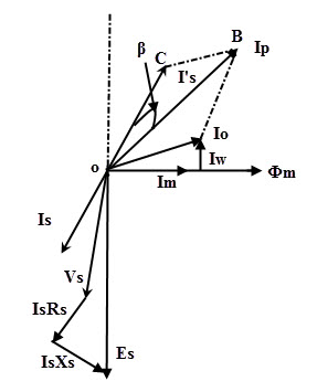
In order to keep the iron core excited, CT draws a primary current. This current excitation current consists of two components, i.e. magnetizing component and wattful component as shown figure. The EMF induced in the secondary circulates secondary current through the burden and due to the inherent resistance and reactance of the secondary winding causes voltage drop in secondary. In the above phasor, I2 is referred to the primary (shown in dotted line) so there exists an angle beta between primary and secondary currents.
Ratio Error
In the above phasor, I1 or primary current consists of the excitation current component. Hence, by considering the triangle OBC, we can get the actual ratio error in terms of the vector components of I2, Io (in turn it depends on magnetizing and wattful components) and I1. And also, secondary current gets affected by its winding resistance and reactance and also by the power factor of the burden. But the nominal or rated current ratio is exactly equal to the ratio of secondary to primary turns. Therefore, the ratio error of the CT is defined as the variation in actual ratio of transformation from nominal ratio.
Current or Ratio Error = (Nominal ratio – Actual ratio) / Actual ratio
= (Kn – R) / R × 100 %
Phase Angle Error
In a perfect current transformer the secondary current must be displaced exactly by 180 degrees from the primary current. In other words, there should be a zero phase angle between primary current and reversed secondary current. In the above phasor diagram, the reversed secondary current leads the primary current by certain angle hence introduces phase angle error. If the reversed secondary current lags the primary current, the phase displacement is negative while it leads, the phase angle is positive.
To reduce these errors in CTs, the exciting or no load current must be kept small and also the load angle of the secondary load must be small. For having these requirements core should have a low core loss and low reluctance to minimize the wattful and magnetizing components of the exciting current. Also, by decreasing the number turns in secondary and reducing the secondary impedance results these errors minimum.
Applications of Current Transformers
The current transformers are used in a wide variety of applications ranging from power system control to the precise current measurement in industrial, medical, automotive and telecommunication systems. Some of the applications include
- Extending the range of measuring instruments such as ammeter, energy meter, KVA meters, wattmeter, etc.
- Differential circulating current protection systems.
- Distance protection in power transmission systems.
- Over current fault protection.

One Response
great information about CT, i need more info about ct use in measuring purpose also CT burden.