In this tutorial, we will learn about Thevenin’s Theorem. It is an important theorem in the field of electrical circuit analysis and is considered to be simpler than Kirchhoff’s laws.
Introduction
For many linear circuits, analysis is greatly simplified by the use of two circuit reduction techniques or theorems as Thevenin’s and Norton’s theorems. The Thevenin’s theorem is named after a French engineer, M. L. Thevenin’s in 1883 and Norton’s theorem after a scientist E. L. Norton.
By using these theorems a large or complex part of a network is replaced with a simple equivalent. With this equivalent circuit, we can easily make necessary calculations of current, voltage and power delivered to the load (as the original circuit delivers). This type of application ensures to select the best value of the load resistance. Let us see in detail about Thevenin’s theorem.
Why Do We Use Thevenin’s Theorem?
In most of the applications, a network may consists of a variable load element, while other elements are constant. The best example is our household outlet which is connected to different appliances or loads. Therefore, if desired, it is necessary to calculate voltage or current or power in every element in a given circuit for every change in variable component.
This repeated procedure is somehow complicated and burdensome. Such repeated computations are avoided by introducing an equivalent circuit for a fixed part in circuit so that circuit analysis with change in load resistance becomes easy.
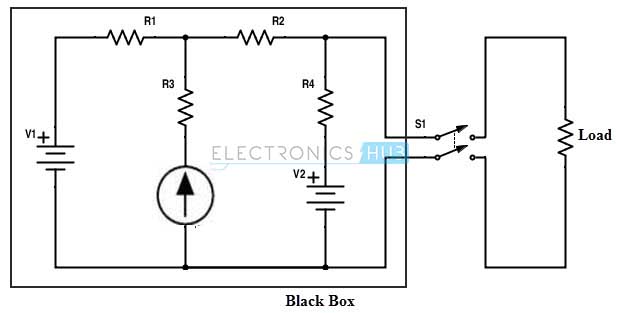
Consider the above simple DC circuit where the current flowing through the load resistance can be determined by using different techniques like mesh analysis or nodal analysis or superposition methods. Suppose the load resistance is changed to some other value than previous then we have to apply any one of these methods again.
This tedious method of applying reduction technique for every load change is avoided by replacing the fixed part of a circuit (inside the black box) with a practical voltage source nothing but a manifestation of Thevenin’s theorem. In practice, the Thevenin’s theorem helps to find the maximum power delivered to the speakers which are supplied from the amplifier in a transistor power amplifier.
Thevenin’s Theorem Statement
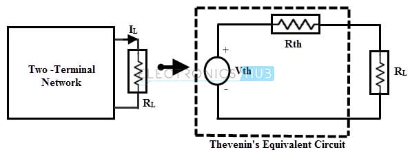
The Thevenin’s theorem states that any linear two terminal circuit consisting of sources and resistors connected to a given load RL can be replaced by an equivalent circuit consisting a single voltage source of magnitude Vth with a series resistance Rth across the terminal of RL.
The below figure shows the Thevenin’s model of two terminal network where the current through the load is same therefore, these two circuits are equivalent to each other.
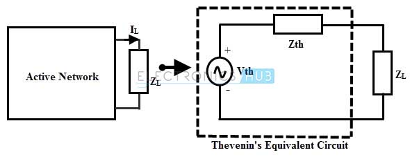
Similar to the DC circuits, this method can be applied to the AC circuits consisting of linear elements like resistors, inductors, capacitors. Like thevinin’s equivalent resistance, equivalent thevinin’s impedance is obtained by replacing all voltage sources by their internal impedances.
In AC circuits the thevenin’s theorem can be stated as any two terminal, linear bilateral circuit consisting of linear elements and active sources connected across the terminal of ZL can be replaced by a single equivalent voltage source of Vth with a single impedance Zth across the two terminals of ZL.
Steps to Analyse the Thevenin’s Theorem
The following are the steps to simplify the circuit so that the load current is determined using Thevenin’s theorem.
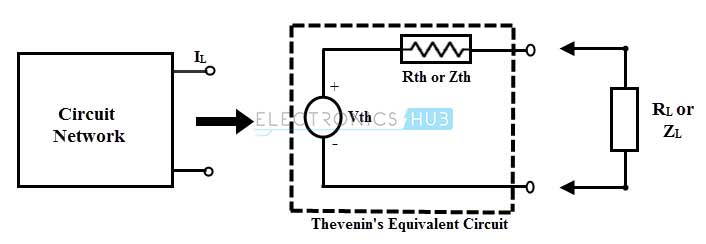
1. Consider the given circuit and disconnect the load resistance RL (load impedance ZL) or branch resistance (branch impedance in AC circuit) through which current flow is to be calculated.
2. Determine the open circuit voltage Vth across the load after disconnecting RL. For finding Vth, one can apply any methods from available circuit reduction techniques like mesh analysis, nodal voltage method, superposition, etc. Or simply, we can measure the voltage at the load terminals using a voltmeter.
3. Redraw the circuit by replacing all the sources with its internal resistances (Internal impedances in case of AC circuit) and make sure that voltage sources are to be short circuited and current sources to be open circuited (for ideal sources).
4. Calculate the total resistance Rth (or Zth) that exist between the load terminals.
5. Insert this equivalent resistance Rth (or Zth) in series with voltage Vth and this circuit is referred as the Thevenin’s equivalent circuit.
6. Now reconnect the load resistance (load impedance ZL) across the load terminals and calculate the current, voltage and power of the load by simple calculations.
In DC circuit,
Load current,
IL = Vth/ (RL + Rth)
Voltage across the load,
VL= RL × Vth/ (RL + Rth)
Power dissipated in the load resistance,
PL = RL × IL2
In case of AC circuit Load current,
IL1 = Vth/ (ZL + Zth)
Voltage acorss the load,
VL= ZL × Vth/ (ZL + Zth)
Power dissipated in the load resistance, PL = ZL × IL12
Example of Finding Equivalent Circuit to DC circuit
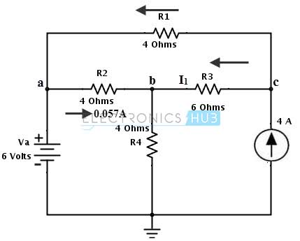
Consider the DC circuit shown in below. We are going to find the current through the resistance R2 = RL = 2 ohms (connected between terminals a and b) by applying Thevenin’s theorem.
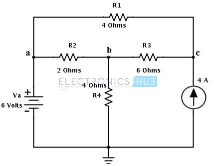
1. Remove the load resistance R2 or RL and assume the closed path direction towards point C.
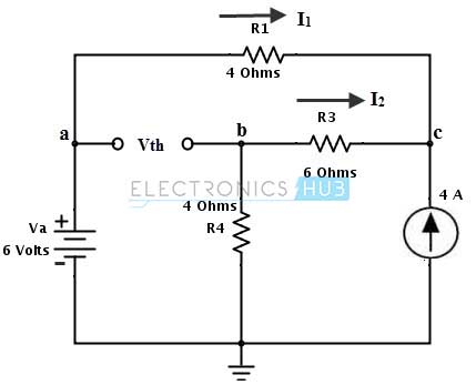
2. Apply nodal analysis at node C to calculate the thevenin’s voltage Vth.
By applying KCL at node C we get
4 + I1 + I2 = 0
4 + (6 – Vc)/ 4 + (0 – Vc)/ 10 = 0
Vc = 15.714 Volts
Then, the currents in each branch can be determined as
I1 = Va – Vc/ 4
= 6 – 15.714/4
= 2.0715 Amps
I2 = 0 – Vc/ 10
= – 15.714/ 10
= – 1.571 Amps
The negative symbol indicates that current is flowing from node C to their respective point (as ‘a’ and ground points for I1 and I2 respectively).
By redrawing the circuit with these currents and by applying KVL, the voltage across the terminal ab is determined as,
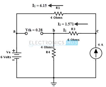
Vth = Va – Vb (with respect to ground terminals)
= Va – (I2× R4)
= 6 – (1.571 × 4)
= 0.28 Volts
3. Next step is to replace all the sources with their internal sources. Consider that voltage source is an ideal source so the internal resistance is zero, therefore it is short circuited and the current source is an ideal current source therefore it has infinite resistance hence it is open circuited. Then the equivalent Thevenin’s resistance circuit is shown below.
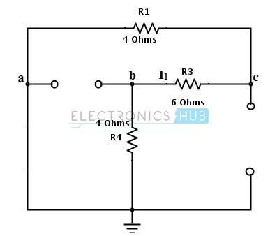
4. Next, we have to find the Thevenin’s equivalent resistance Rth by looking at the terminals a and b (load terminals).
Rth = [(R1 + R3) × R4] / [(R1 + R3) + R4] (parallel resistors)
= 10 × 4 / 10 + 4
= 2.85 Ohms
5. By placing the above calculated voltage source in series with equivalent resistance forms Thevenin’s equivalent circuit as shown in below figure.
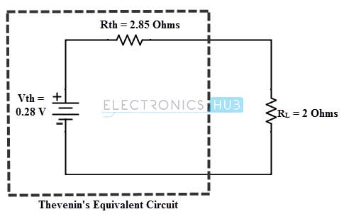
By reconnecting the load resistance across the terminals a and b, we calculate the current flowing through the load as
IL = Vth / (Rth + RL)
= 0.28/ (2.85 + 2)
= 0.057 Amps
And below figure shows the original circuit where the current through the load resistance is indicated.
We can also find the currents through the load by changing the value of the load resistor as
When RL = 8 ohms
IL = 0.28 / (2.85 + 8)
= 0.02Amps
When RL = 12 ohms
= 0.28 / (2.85 + 12)
= 0.01 Amps
Example of Finding Equivalent Circuit to AC circuit
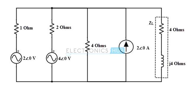
Consider the below AC circuit to which we are going to find the current through the impedance 4+ 4j ohm using thevenin’s theorem.
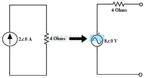
In the above circuit, the current source of 2∠0 in parallel with 4 ohm resistor. And hence, this can be converted into a voltage source 8∠0 with a series resistance of 4 ohms as shown in figure.
After making the above change, the circuit is redrawn by disconnect the load terminals as shown in below figure.

Assume the mesh currents as shown in modified diagram and KVL equation of the meshes are
2∠0 – I1 – 2(I1– I2) – 4∠0 = 0
– 3I1 + 2I2 = 2 …….(1)
For mesh 2
4∠0 – 2(I2 – I1) – 4I2– 8∠0 = 0
2I1 – 6I2 = 4 …….(2)
By solving above two equations, we get
I2 = –1.142∠0 A
Therefore,
Vth = 8∠0 – 4× (1.142∠0)
= 3.43∠0 V
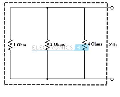
The equivalent impedance,
Zth = 1/ (1 + (1/2) + (1/4))
= 0.574 ∠0
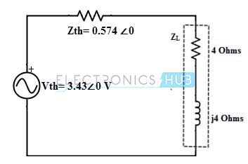
Therefore, the current through the 2 + 2j impedance is given as,
IAB = Vth/ Zth + ZL
= 3.43∠0/ (0.574 ∠0 + 4 + 4j)
= 3.43∠0 / (6.07 ∠41.17)
= 0.56∠ – 41.17 A
Limitations of Thevinen’s Theorem
• If the circuit consists of non linear elements, this theorem is not applicable.
• Also to the unilateral networks it is not applicable.
• There should not be magnetic coupling between the load and circuit to be replaced with the thevinen’s equivalent.
• There should not be controlled sources on the load side which care controlled from some other parts of the network.

One Response
It’s relevant to my class, so keep up the good work. Thank you and more power.
Truly yours,
Engr. Ellezer G. Casiño