Resistors can be connected in series connection alone or in parallel connection alone. Some resistor circuits are made from combination of series and parallel networks to develop more complex circuits. These circuits are generally known as Mixed Resistor Circuits. Even though these circuits have combined series and parallel circuits, there is no change in the method of calculating the Equivalent Resistance. The basic rules of individual networks like “same current flows through resistors in series” and “voltage across resistors in parallel is same” are applicable to mixed circuits.
Resistors in Series and Parallel
An example of mixed resistors circuit is shown below
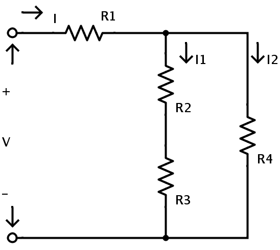
It consists of four resistors R1, R2, R3 and R4 in a mixed resistor circuit combination. The supply voltage is V and the total current flowing in the circuit is I. The current flowing through the resistors R2 and R3 is I1 and the current flowing through the resistor R4 is I2.
Here the resistors R2 and R3 are in series combination. Hence applying the rule of resistors in series combination the equivalent resistance of R2 and R3 is given as
RA = R2 + R3
Here RA is the equivalent resistance of R2 and R3
Now the resistors R2 and R3 can be replaced by a single resistor RA. The resulting circuit is shown below.
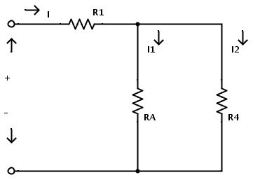
Now the resistors RA and R4 are in parallel combination. Hence by applying the rule of resistors in parallel combination the equivalent resistance of RA and R4 is
RB = RA × R4 / (RA + R4)
Here RB is the equivalent resistance of RA and R4
Now we can replace the resistors RA and R4 with a single resistor RB.After replacing the resistors the resulting circuit is shown below.
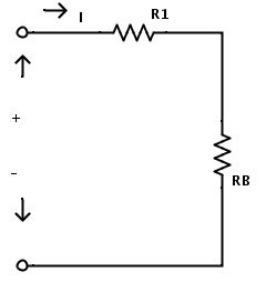
Now the circuit consists of only two resistors. Here also the resistors R1 and RB are in series combination. Hence by applying the rule of resistors in series the total circuit equivalent resistance is given as
REQ = R1 + RB
Here REQ is the total circuit equivalent resistance. Now the resistors R1 and RB can be replaced by a single resistor REQ.
The final equivalent circuit for above complex circuit is shown below.
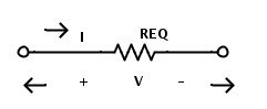
Though they look complicated, the mixed resistor circuits can be reduced to a simple circuit consisting of only one voltage source and a single resistor by following the simple rules of resistors in series and resistors in parallel.
Resistors in series and parallel Example
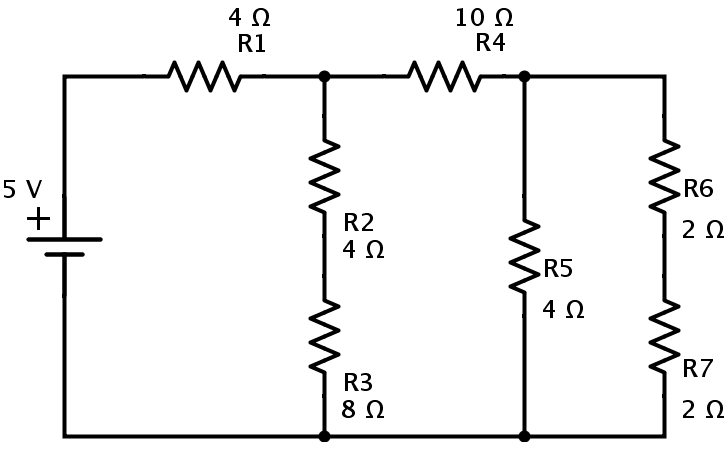
Let us calculate the equivalent resistance for the below circuit which consists of 7 resistors R1 = 4 Ω, R2 = 4 Ω, R3 = 8 Ω, R4 = 10 Ω, R5 = 4Ω, R6 = 2 Ω and R7 = 2Ω.The supply voltage is 5 V.
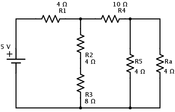
Now the resistors R6 and R7 are in series combination. If the equivalent resistance of R6 and R7in series is Ra, then
Ra = R6 + R7 = 2+2 = 4Ω
The resulting circuit is reduced to the one shown below.
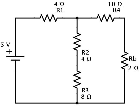
In the above circuit the resistors Ra and R5 are in parallel combination. Hence the equivalent resistance of Ra and R5 is
Rb = (Ra × R5) / (Ra + R5) = (4 × 4) / (4 + 4) = 2Ω.
Then the simplified circuit is shown is below.
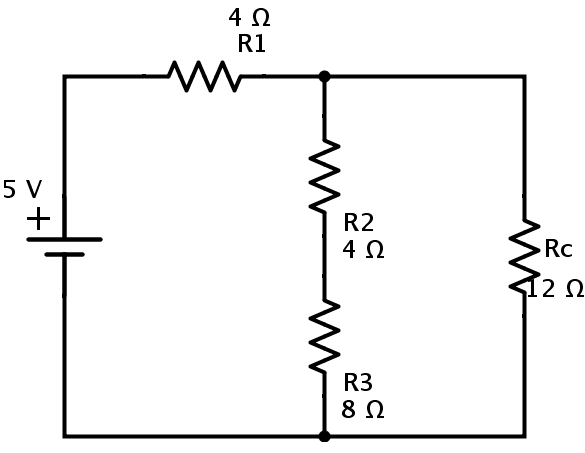
In this circuit the resistors R4 and Rb are in series combination.
Rc = R4 + Rb = 10 + 2 = 12 Ω.
Now we can replace the resistors R4 and Rb with resistor Rc as shown below.
In the above circuit again the resistors R2 and R3 are in series combination. If Rd is the equivalent resistance of R2 and R3then
Rd = R2 + R3 = 4 + 8 = 12 Ω.
The equivalent circuit is
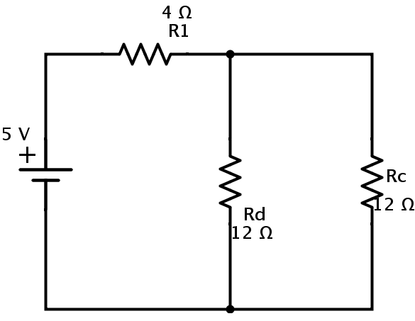
Here resistors Rc and Rd are in parallel combination. Let Rp be the equivalent resistance of Rc and Rd in parallel. Then
Rp = (Rc × Rd) / (Rc + Rd) = (12 × 12) / (12 + 12) = 6 Ω.
The resulting circuit is
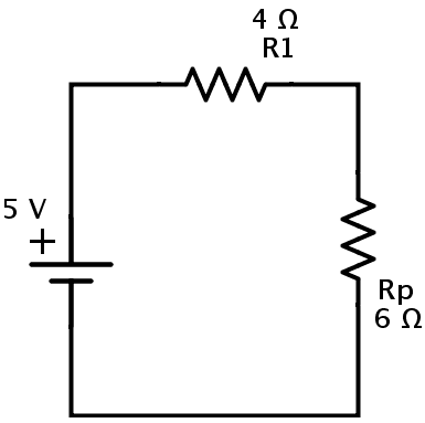
Here, the resistors R1 and Rp are in series combination. Let REQ be the equivalent resistance of this combination.
Then
REQ = R1 + Rp = 4 + 6 = 10 Ω.
This is the equivalent resistance of the circuit. Hence the given circuit can be finally redrawn as
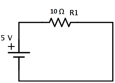
The current in the circuit can be calculated from Ohm’s law
I = V / REQ = 5 / 10 = 0.5 A
Resistor Network
Let us calculate the equivalent resistance for a complex resistor circuit.
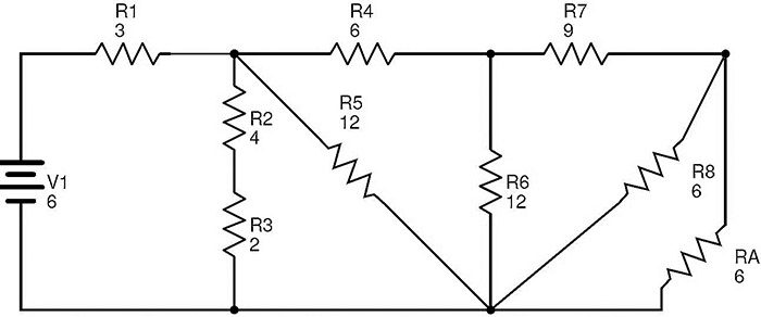
The below circuit consists of ten resistors R1 to R10 connected in a combination of series and parallel connections.
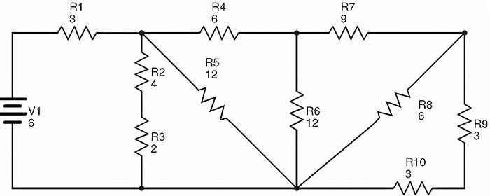
The values of the resistances mentioned in the circuit are in Ohms (Ω) and the supply voltage is in Volts (V).
Here the resistors R9 and R10 are in series combination. Let RA is the equivalent resistance of this combination.
Therefore RA = R9 + R10 = 3 + 3 = 6 Ω.
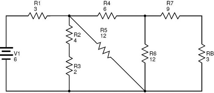
The circuit after replacing R9 and R10 with RA is
In this circuit, the resistors R8 and RA are in parallel combination. Then the equivalent resistance of R8 and RA is
RB = (R8 × RA) / (R8 + RA) = (6 × 6) / (6 + 6) = 3 Ω.
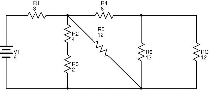
Now replacing R8 and RA with RB, we get the following circuit.
In this circuit, the resistors R7 and RB are in series combination.
RC = R7 + RB = 9 + 3 = 12 Ω.
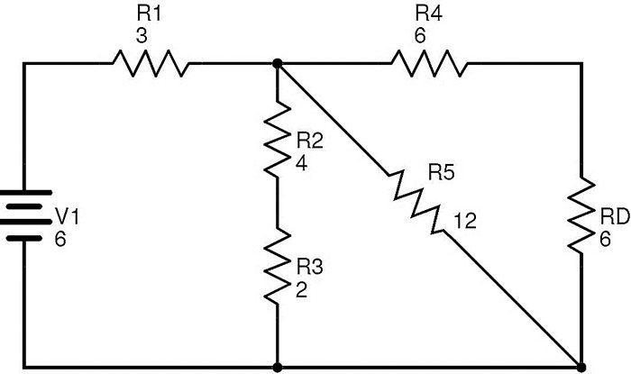
The equivalent circuit after replacing R7 and RB with RC is
It is clear that the resistors R6 and Rc are in parallel combination. If RD is the equivalent resistance of this combination, then
RD = (R6 × Rc) / (R6 + Rc) = (12 × 12) / (12 + 12) = 6 Ω.
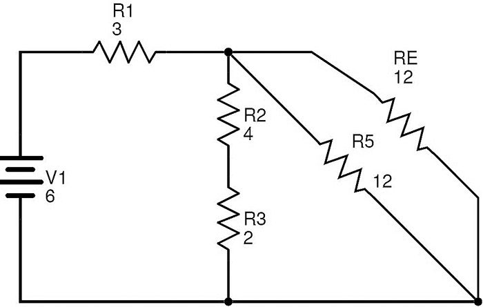
The circuit with R¬D replacing R6 and Rc is
Now the resistors R4 and RD are in series combination. If RE is the equivalent resistance of R4 and RD then
RE = R4 + RD = 6 + 6 = 12 Ω.
The resulting reduced circuit after replacing R4 and RD with RE is
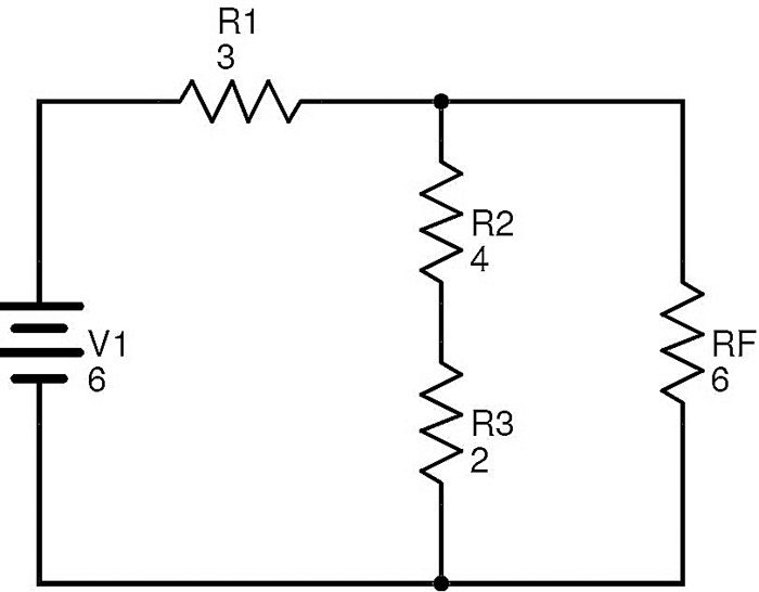
In this circuit, the resistors R5 and RE are in parallel combination.
Let RF be the equivalent resistance of R5 and RE in parallel.
Then
RF = (R5 × RE) / (R5 + RE) = (12 × 12) / (12 + 12) = 6 Ω.
The simplified circuit is as shown below.
Here the resistors R2 and R3 are in series. If RG is the equivalent of this combination, then
RG = R2 + R3 = 4 + 2 = 6 Ω.
After replacing R2 and R3 with RG, the circuit will be transformed to
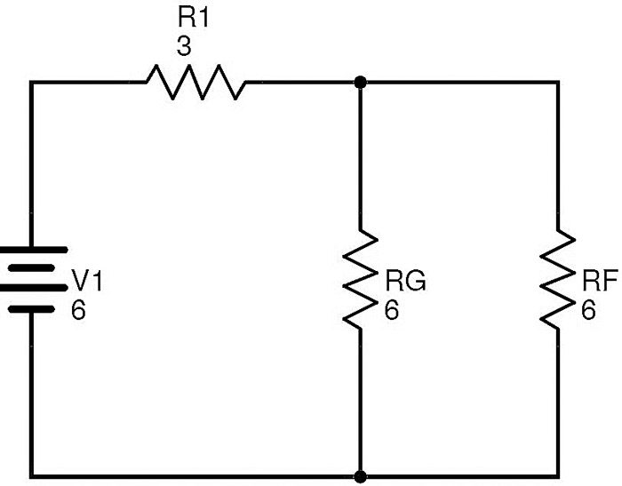
The resistors RF and RG are in parallel.
Let RT be the equivalent of this combination.
Then RT = (RF × RG) / (RF + RG) = (6 × 6) / (6 + 6) = 3 Ω.
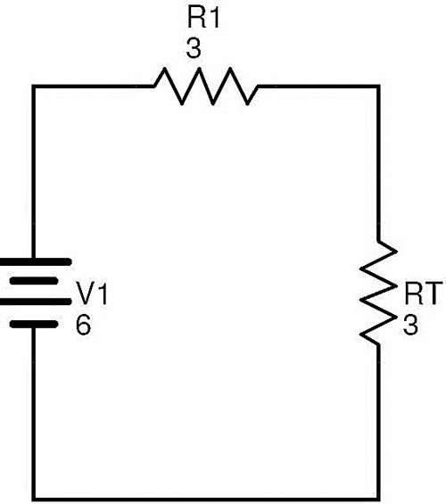
Now the resistors R1 and RT are in series. If REQis the total circuit equivalent resistance, then REQ = R1 + RT = 3 + 3 = 6 Ω.
Finally the above complex circuit can be redrawn as follows
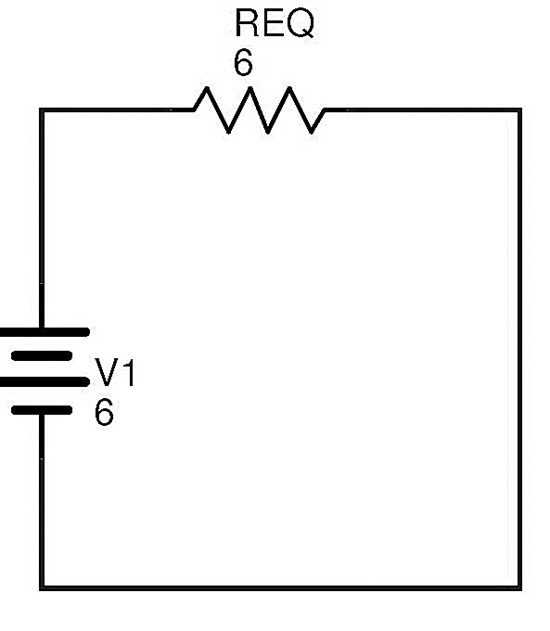
The total current in the circuit can be calculated using Ohm’s law
I = V1 / REQ = 6 / 6 = 1 A
Hence any complex resistive circuit consisting of number of resistors connected in combination of both series and parallel combinations can be reduced by first identifying the simple parallel resistor branches and series resistor branches. The equivalent resistance of these simple branches is calculated and the branches are replaced with the equivalent resistor. This process reduces the complexity of the circuit. By continuing this process we can replace a complex resistive circuit with a single resistor.
There are some complex resistive circuits which cannot be reduced to simple circuits by simply applying the rules of series resistive combinations and parallel resistive combinations.Circuits like T-Pad Attenuators and some complex resistive bridge networks are examples of such complex resistive circuits. In order to simplify these complex resistive circuits, a different approach is to be followed.
Some complex resistive circuits can be reduced by using Kirchhoff’s Current Law and Kirchhoff’s Voltage Law.
To find the currents and voltages in a complex resistive circuit just by using Ohm’s law might not possible. For such type of circuits Kirchhoff’s Circuit Laws will be helpful.
Kirchhoff’s Circuits laws are based on the concept of conservation of current and energy in a circuit. There are two Kirchhoff’s Circuit laws. First is Kirchhoff’s Current Law which deals with current at node and the second is Kirchhoff’s Voltage Law which deals with voltage in a closed circuit.
Kirchhoff’s Current Law states that “The current entering a node is equal to the current leaving the node because it has no other place to go and no current is lost in the node.”
In simple words, the Kirchhoff’s Current Law states that the sum of currents entering a node is equal to sum of currents leaving the circuit.
Kirchhoff’s Voltage Law states that “the total voltage in a closed loop is equal to sum of all voltage drops in that loop.”
In simple words, the Kirchhoff’s Voltage Law states that the directed algebraic sum of voltages in a closed loop is equal to zero.
With the help of these two laws the values of currents and voltages in any complex circuit can be calculated.
Still we may have some complex resistive circuits in which it is difficult to identify the equivalent resistance, in such situations we will use Star Delta Transformations of resistors in order to simplify the resistor networks.

3 Responses
How would you calculate the current going through the various resistors?
For example what is the current through the R10, 3 Ohm resistor?
That was really helpful. I got no word for this. thankyou so so so so much
The current is 1 amp??