In this tutorial, we will learn about Norton’s Theorem. Together with Thevenin’s Theorem, Norton’s Theorem forms an important concept in the field of electrical circuit analysis.
Outline
ToggleIntroduction
In contrast to the Thevenin’s theorem, Norton’s theorem replaces the part of the circuit with an equivalent circuit that constitute a current source and a parallel resistance. This theorem is an extension of the Thevenin’s theorem, proposed by E. L. Norton in 1926.
Similar to the Thevenin’s theorem, it is also used to calculate load variables such as load voltage, load current and load power with simple calculations over other circuit reduction techniques. Thus, this theorem is also called as the dual of the Thevenin’s theorem. In most of the cases the choice of load resistance to transfer maximum power to the load is decided by either Thevenin’s or Norton’s theorems.
Norton’s Theorem Statement
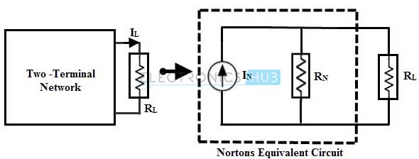
Norton’s theorem states that , any two terminal linear network that constitute independent sources and linear resistances can be replaced with an equivalent circuit , consisting of a current source with a parallel resistor.
Magnitude of this equivalent current source is equal to the short circuit current flowing through the load terminals and the equivalent resistance is the resistance at the load terminals, when all the sources in a given circuit are replaced by their internal resistances.
In below figure a part of a network , constituting of sources (either voltage or current or both) and resistances is replaced with a current source and a parallel resistor such that current flowing through the load is same in both cases.
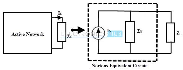
For an AC circuit it can be stated as , any active two terminal network consisting of independent sources and impedance can be replaced with an equivalent circuit consisting of a constant current source with a parallel impedance.
The value of the current source is equal to the current flow through the short circuited terminals of the network. And the parallel impedance is the equivalent impedance viewed from the short circuited terminals when all the sources are replaced with their internal impedance.
Steps to Analyse the Norton’s Theorem
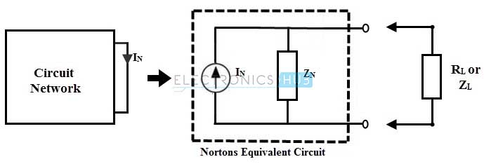
To find the load variables using Norton’s theorem, Norton’s equivalent parameters have to be determined. Those are Norton current or magnitude of equivalent current source and Norton resistance Rn or impedance ZN. The following steps are required to determine them.
1. Consider the given circuit and short the load terminals after disconnecting the load resistance (or impedance in case of AC circuit) from output or load terminals.
2. Determine the short circuit current IN, through the shorted terminals by applying any of the circuit reduction techniques like Mesh analysis or nodal analysis or superposition theorem. Or simply measure the load current using the ammeter experimentally.
3. Redraw the given circuit by replacing all the practical sources in the circuit with their internal voltages or simply short circuit voltages sources and open circuit the current sources . And also make sure to open or remove the short circuited terminals of the load.
4. Calculate the resistance (or impedance) that exists between the load terminals by looking from the load terminals. This resistance is equivalent Norton’s resistance RN or (impedance ZN).
5. Insert the resistance (or impedance) in parallel with a current source IN which forms a Norton’s equivalent circuit.
6. Now reconnect the load to the Norton’s equivalent circuit and calculate the current, voltage and power associated with the load as
In DC circuit,
Load current, IL = IN × [RN / (RL + RN)]
Load Voltage, VL = IL × RL
Power dissipated at the load, P = IL2 × RL
In AC circuit,
Load current, IL = IN × [ZN / (ZL + ZN)]
Load Voltage, VL = IL × ZL
Power dissipated at the load, P = IL2 × ZL
Example for Finding Equivalent Circuit to DC Circuit
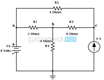
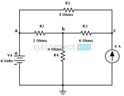
Let us consider the same DC circuit in Thevenin’s theorem example to apply the Norton’s theorem to find the current flow through branch ab i.e., through the load resistance RL = R2 = 2 ohms.
1. Disconnect the load resistance and short the load terminals a and b. Represent the current flow direction in every loop as shown in figure.
2. Apply the mesh analysis for each loop to find the current flow IN through the shorted terminals.
By applying KVL to loop 1 we get
6 – (I1 – I2) R4 = 0
Substituting I2 = -4A
I1 = 6 – 16 / 4 = – 2.5 A
By applying KVL to Loop 3 we get
– I3R1 – (I3 – I2)R3 = 0
-4I3 – 6 (I3 + 4) = 0
– 10I3 = 24
I3 = – 2.4 A
Therefore In = I1 – I3
= -2.5 + 2.4
= 0.1A which is flowing from a to b.
3. Next step is to determine the equivalent resistance RN. To compute this resistance all sources have to be replaced with their internal resistances by removing the short terminals of the load .
Then the total resistance across the terminals a and b, RN = 10 × 4 / 10 + 4
= 2.85 Ohms
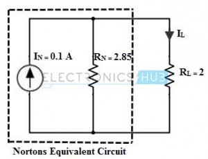
4. By placing above calculated current In in parallel with resistance Rn forms a Norton’s equivalent circuit as shown in figure. To determine the load variables we reconnect the load resistance across the load terminals.
Then Load current IL = IN × [RN / (RL + RN)]
= 0.1 × [2.85/ (2 + 2.85)]
= 0.05 Amps
With the above calculated values, the original circuit is similar to the below shown figure with the representation of load current at branch ab.
For different values of the load resistance the current flow is determined as
When RL = 8 ohms
IL = 0.1 × [2.85 / (8 + 2.85)]
= 0.02 A
When RL = 12 ohms
IL = 0.1 × [2.85 / (12+ 2.85)]
= 0.01 A.
Relation between Norton’s and Thevinin’s Theorems
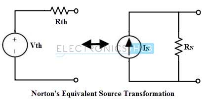
By comparing the above example with example of Thevenin’s example problem, we can observe that Norton’s equivalent circuit of a linear network constitute a Norton current source IN in parallel with a Thevenin’s resistance Rth.
Therefore it is possible to perform a source transformation of Thevenin’s equivalent circuit to get the Norton’s equivalent circuit or vice-versa.
The magnitude of the voltage source (Vth) and a series resistance (Rth) from Norton’s equivalent circuit using source transformation are determined as
Vth = RN × IN and
Rth = RN
For above example
Vth = 2.85 × 0.1
= 0.28 Volts.
Therefore, we can use any of these two methods to analyse the circuit in a simple way. However the advantages of Thevenin’s theorem are also applicable to Norton’s theorem as well. By using these methods one can find the current and voltage values of different load resistance values without doing any complex calculations again and again.
Hence, the Norton’s theorem aids the designing much easier based on the application. The use of these two theorems is decided by the application where these equivalents are required, such as current follower circuits (use Norton’s equivalent) and voltage amplifiers (Thevenin’s equivalent).
Example of Finding Equivalent Circuit to AC Circuit
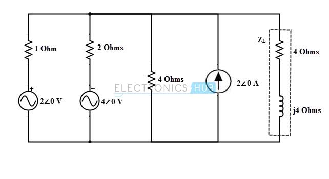
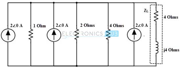
Consider the below AC circuit which was already analyzed using thevenin’s theorem. In this circuit we are going to find the current through the impedance 4+ 4j ohm using Norton’s theorem.
The above circuit consists of two voltage sources which can be transformed into the current source as
Is1 = Vs1/ Rs1
= 2∠0 / 1
= 2 A
Similarly
Is2 = Vs2/ Rs2
= 4∠0/ 2
= 2 A
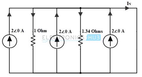
Then the circuit becomes
For applying Norton’s theorem, we disconnect the load impedance and short the load terminals as shown in figure. Assume the current directions as represented in figure.
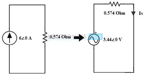
Consider the above figure as single node and the total current becomes 6 amperes and the total parallel combination of resistance is 0.574 ohms. This can be transformed into a voltage source for ease of finding the Norton’s current is given as
Vs = 6 ∠0 × 0.574
= 3.44∠0
Therefore, IN = VN / 0.574
= 3.44∠0 / 0.574
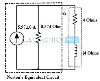
= 5.97∠0 A
The Norton’s equivalent impedance is equal to the circuit equivalent impedance, ZN = 0.574
Therefore the Load current across the 4 + j4 impedance is, IL = IN × [ZN / (ZL + ZN)]
= 5.97∠0× [0.574/ (4 + j4 + 0.574)]
= 3.42 / 6.07∠41.17
= 0.56 ∠-41.17 A
This value is identical to the value obtained in the case thevenin’s example of AC circuit. And hence Norton’s theorem is the dual of thevenin’s theorem. Limitations of Thevenin’s theorem are also applicable for norton’s theorem.

