In this project, we have designed a simple 230V LED Driver circuit, which can drive LED directly from the mains supply.
An LED is a special type of diode used as an Optoelectronic device. Like a PN junction diode, it conducts when forward biased. However, a special feature of this device is its ability to emit energy in the visible band of the electromagnetic spectrum i.e. visible light.
A major concern to drive an LED is to provide an almost constant current input. Often, an LED is driven using batteries or control devices like microcontrollers. However, these have their own disadvantages, for example – low battery life etc.
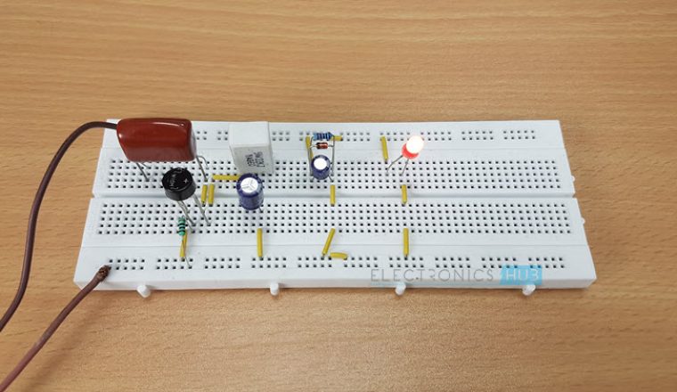
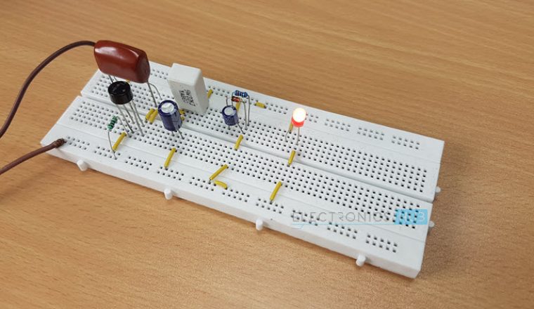
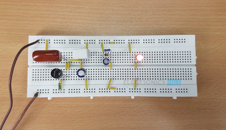
230v LED Driver Circuit
A feasible approach would be driving the LED using AC to DC power supply. Though AC to DC power supply using transformer is quite popular and widely used, for applications like driving loads like LED, it proves to be quite costly and moreover it is not possible to produce a low current signal using transformer.
Keeping in mind all the factors, here we designed a simple circuit driving an LED from 230V AC. This is accomplished using a capacitor based power supply. This is a low cost and efficient circuit and can be used at homes.
Related Post: Bipolar LED Driver Circuit
230v LED Driver Circuit Principle
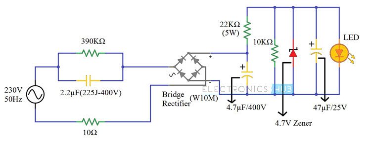
The basic principle behind the 230V LED Driver circuit is transformer less power supply. The main component is the X-rated AC capacitor, which can reduce the supply current to a suitable amount. These capacitors are connected line to line and are designed for high voltage AC circuits.
The X – Rated Capacitor reduces only the current and the AC voltage can rectified and regulated in the later parts of the circuit. The high voltage and low current AC is rectified in to high voltage DC using a bridge rectifier. This high voltage DC is further rectified using a Zener diode to a low voltage DC.
Finally, the low voltage and low current DC is given to an LED.
230v LED Driver Circuit Diagram
Components Required
- 2.2µF Polyester Film Capacitor (225J – 400V)
- 390KΩ Resistor (1/4 Watt)
- 10Ω Resistor (1/4 Watt)
- Bridge Rectifier (W10M)
- 22KΩ Resistor (5 Watt)
- 4.7µF / 400V Polarized Capacitor
- 10KΩ Resistor (1/4 Watt)
- 4.7V Zener Diode (1N4732A) (1/4 Watt)
- 47µF / 25V Polarized Capacitor
- 5mm LED (Red – Diffused)
How to Design a 230V LED Driver Circuit?
First, a 2.2µF / 400V X – Rated Capacitor is connected in line with the mains supply. It is important to pick a capacitor with voltage rating greater than the supply voltage. In our case, the supply voltage is 230V AC. Hence, we used a 400V rated capacitor.
A 390KΩ resistor is connected in parallel with this capacitor to discharge it when the supply is turned off. A 10Ω resistor, which acts as a fuse, is connected between the supply and bridge rectifier.
The next part of the circuit is a full wave Bridge Rectifier. We have used a single chip rectifier W10M. It is capable of handling currents up to 1.5 Amperes. The output of the Bridge Rectifier is filtered using 4.7µF / 400V Capacitor.
For regulating the DC output of the Bridge Rectifier, we are using a Zener Diode. A 4.7V Zener Diode (1N4732A) is used for this purpose. Before the Zener Diode, we have connected a series resistor of 22KΩ (5W) for limiting the current.
The regulated DC is given to the LED after filtering it out using 47µF / 25V Capacitor.
How the 230V LED Driver Circuit Works?
A simple, transformer less 230V LED Driver Circuit is built in this project. The main components of this project are the X – Rated Capacitor, the Zener Diode and the resistor which limits the current in the Zener Diode. Let us see the working of this project.
First, the 2.2µF X – Rated Capacitor (225J – 400V) will limit the AC current from the mains supply. In order to calculate this current, you have to use the Capacitive Reactance of the X – Rated Capacitor.
The formula for calculating the Capacitive Reactance is given below.
![]()
So, for 2.2µF Capacitor, XC can be calculated as follows.
![]()
So, from Ohm’s Law, the current that the capacitor allows is given by I = V/R.
Hence, the current through the capacitor is = 230/1447.59 = 0.158 Amperes = 158mA.
This is the total current that enters the bridge rectifier. Now, output of the Bridge Rectifier is filtered using a Capacitor. It is important to select an appropriated voltage rating for this capacitor.
The input to the Bridge Rectifier is 230V AC, which is the RMS Voltage. But the maximum voltage at the input of the Bridge Rectifier is given by
VMAX = VRMS x √2 = 230 x 1.414 = 325.26 V.
Hence, you need to use a 400V rated filter capacitor. The Rectified DC voltage is around 305V. This must be brought down to a usable range for lighting up the LED. Hence, the Zener Diode is used in the project.
A 4.7V Zener Diode is used for this purpose. There are three important factors associated with the Zener Diode that is acting as a regulator: A Series Resistor, Power Rating of that Resistor and the Power Rating of the Zener Diode.
First, the Series Resistor. This resistor will limit the current flowing through the Zener Diode. The following formula can be used in selecting the series resistor.
![]()
Here, VIN is the input voltage to the Zener Diode and is = 305V.
VZ is the Zener Voltage (which is same as the load voltage VL) = 4.7V.
IL is the load current i.e. the current through the LED and is = 5mA.
IZ is the current through the Zener Diode and is = 10mA.
Therefore, the value of the Series Resistor RS can be calculated as follows.
![]()
Now, the Power Rating of this Resistor. The Power Rating of the series resistor is very important as it determines the amount of power the resistor can dissipate. To calculate the power rating of the Series Resistor RS, you can use the following formula.
![]()
Finally, the Power Rating of the Zener Diode. You can use the following formula to calculate the Power Rating of the Zener Diode.
![]()
Based on the above calculations, we have chosen the series resistor of 22KΩ Resistance rated at 5W and a 4.7V Zener Diode rated at 1W (actually, a quarter Watt Zener would suffice).
The rectified and regulated voltage with limited current is given to the LED.
Advantages
- With the help of this 230V LED Driver Circuit, we can drive LEDs directly from the main supply.
- This project is based on a Transformer Less Power Supply. Hence, the final build won’t be a large one.
Applications of 230V LED Driver Circuit
- This circuit can be used for home lightening systems.
- It can be used as an indicator circuit.
- One can fix this circuit with the door bell to give indication.
Limitations of 230V LED Driver Circuit
- Since 230V AC supply is being directly used here, this circuit can be dangerous.
- This circuit is best suited for domestic applications using single phase supply. This is because, in case of three phase supply, if any of the phases accidently touches the input terminal, it can prove to be quite dangerous.
- The capacitor can produce spikes at mains fluctuations.

21 Responses
kindly explain each component used in the circuit
Wow – what an effort…
If you only want to signalize 230…240 VAC power supply is present … you will need 3 parts only::
1. low power LED with 2 mA current (not 20 mA!),
2. resistor 120 kOhm /0.5 W (typical 0.6W)
3. diode 1 N4007 (1000V /for LED negative voltage protection)
all elements switched in line.
Dear Sir, kindly help me in designing the circuit for 7W led. Details of LED (Load)
1. Each LED specs is as: 9V/100ma , 1W
2. 7 nos of LED connected in series at Load .
Request to help in getting the ratings of the components used.
Regards
Vevek Siingh
The description of driver circuit for LED is really very good . I have got better idea after reading Ur concept . Thanks
very nice article. useful form me to correct my table light with magnifying glass.
Clear explaination great english
Thank you sir, but i have 3 phase connection at home, so is it become dangerous??
According to this circuit, how much power does this ice cost?
W? Please tell me
How you know, that the Zenere diode current is 10mA???
what about driving 10x 100w led (30-36v/3 amp)?
Sir here what is the use of 10k resistor..
If I need 100v & 100mA output then how can I use this?
Of course your design clears the basic operation of LED tube with many protection system.
Thanks a lot.
Can we use this circuit to drive 7Watt LED bulb.
Sir Very good effort
Kindly send me circuit diagram for 30 smd led in series
Want to use smd 2835,0.2 watt ,3.2volts cool white
Thanks
My requirement raw Material of led bulb
How i protect LED bulb from high voltage
I’m not an expert but I have read that Varistors can be used across the mains.
4.5W into resistor for burning an LED? Not very efficient.
Thank you for clear explanation.
The line at Rs calculation says: Here, Vin is the input voltage to the Zener Diode and is = 305V
Can someone kindly explain to me: How the voltage is calculated to be 305 when the output of rectifier is (Vmax = Vrms x √2 = 230 x 1.414 = 325.26 V)
Great explanation. Useful for students. Thank you Sir