Understanding the basics of electric circuits is very essential for students, engineers and electricians. The two basic types of electric circuits are Series Circuits and Parallel Circuits. We can simplify any complex electric circuit using Series, Parallel or their combination. So, in this guide, let us take a closer look at the Parallel Circuit, its characteristics, current and voltage flow in a parallel circuit and also some important equations.
What is a Parallel Circuit?
Before getting to know about the parallel circuit, let us quickly go through the basics of an electric circuit. To put in simple words, an electric circuit is collection of components and devices such as resistors, capacitors, inductors, transistors, diodes, voltage and/or current source and many more that are connected using metal conductors.
In the electric circuit, electrons flow from the negative terminal of the power supply (usually a voltage source) through the metal wires, different components and finally back to the positive terminal of the power supply.
If the circuit is designed/laid-out in such a way that the electrons can only flow in one path, the circuit is known as a Series Circuit. On the contrary, if the circuit has multiple paths for the electrons to flow, then the circuit is known as a Parallel Circuit.
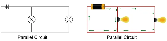
The following image shows a simple illustration of series and parallel circuits using a voltage source and some light bulbs.
Image
Rules Associated with Parallel Circuits
In series circuits, the voltage is proportionately divided across all the circuit components. But in a parallel circuit, the same voltage is present across all the parallel branches and this voltage is equal to the source voltage.
For example, in the following parallel resistive circuit, if VS is the source voltage and V1, V2 and V3 are the respective branch voltages, then
VS = V1 = V2 = V3
Coming to the current, in a series circuit, one current flows in the circuit but it is different in a parallel circuit. The source current in a parallel circuit is divided among the parallel branches depending on the resistance of that branch.
If ‘IS’ is the source current and I1, I2 and I3 are the respective branch currents in the above circuit, then
IS = I1 + I2 + I3
We can apply Ohm’s Law at the individual branch level to determine the current.
Different Components in Parallel Configuration
Now that we have seen the basics of parallel circuit and also couple of its important equations, let us now proceed to determine the equivalent values of different circuit components in parallel.
Resistors in Parallel
In a series resistive circuit, the equivalent resistance of all the resistors in series is equal to the sum of individual resistor values. But when we connect a bunch of resistors in parallel, the equivalent resistance is equal to:
1/REQ = 1/R1 + 1/R2 + 1/R3
Capacitors in Parallel
Coming to capacitors in parallel, if C1, C2 and C3 are connected in parallel and CEQ is the equivalent capacitance, then
CEQ = C1 + C2 + C3
Inductors in Parallel
Finally, we have inductors in parallel. Similar to resistors in parallel, when a bunch of inductors are connected in parallel, the inverse of the equivalent inductance is equal to the sum of inverse of individual inductance. You can better understand this with the help of the following formula.
1/LEQ = 1/L1 + 1/L2 + 1/L3
Conclusion
Parallel Circuits are an essential part of all electrical circuits. We use them in our daily lives in the form of residential wiring. So, understanding the basics of parallel circuits, how to determine the voltage, current and resistance in a parallel circuit is very important.
