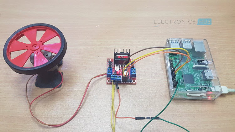
Let us continue exploring Raspberry Pi and its features by Interfacing L298N Motor Driver with Raspberry Pi and control a DC Motor with the help of a Python Script. In this project, we will learn about L298N Motor Driver and how the Raspberry Pi L298N Motor Driver Module Interface works.
Overview
Interfacing L298N Motor Driver Module with Raspberry Pi will allow us to control a DC Motor (in fact, you can control two DC Motors).
When I say control a DC Motor, I mean you can start a motor, stop it, make it rotate in forward direction, backward directions, increase the speed of rotation and also decrease the speed.
For this, I’ll be using the L298N Motor Driver Module. If you remember, I have already made a project on CONTROLLING A DC MOTOR WITH RASPBERRY PI using L293D Motor Driver.
How different will it be for controlling a DC Motor using Raspberry Pi with L293D and L298N? Well, there won’t be much of a difference as essentially both these modules serve the same purpose.
But it is always nice to learn about something new and implement it into a project. So, first, let me take you through a simple introduction to L298N Motor Driver Module.
L298N Motor Driver Module
In recent times, L298N Motor Driver Module has become the favorite choice of hobbyists and makers when it comes to DC Motor Control. It became so popular that the module is now available at a very low cost.
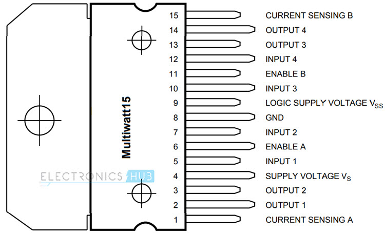
The L298N Motor Driver Module is based on the powerful L298N Motor Driver IC. The pin diagram of the L298N Motor Driver IC is shown in the image below. This IC, along with few other extra components make up the L298N Motor Driver Module.
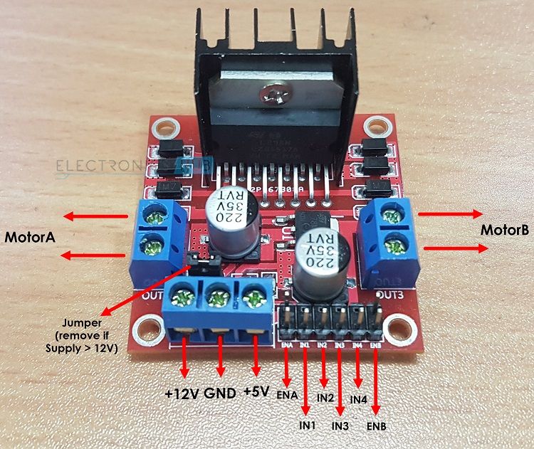
The above image shows the L298N Motor Driver Module with names of all the components on it. To name a few, it contains screw terminals for connecting motors and power supply, male headers for connecting different pins like enable, IN1, IN2 etc.
NOTE:
- There is jumper near the power supply terminals of the L298N Motor Driver Module. If it is connected, it will enable the on-board 5V regulator, which supplies +5V logic supply for L298N IC.
- This must be used only if the supply voltage is less than or equal to +12V. If it is more than +12V, then disconnect the jumper to disable the regulator.
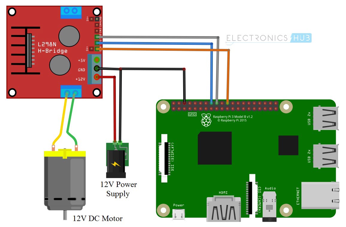
Circuit Diagram of Raspberry Pi L298N Interface
The following image shows the circuit diagram of the Raspberry Pi L298N Motor Driver Module Interface. The circuit diagram is made with the help of Fritzing App.
Components Required
- Raspberry Pi
- L298N Motor Driver Module
- 12V DC Motor
- 12V Power Supply for Motor and Motor Driver
- Power Supply for Raspberry Pi
- Connecting Wires
Circuit Design
The design of the Raspberry Pi L298N Motor Driver Interface Circuit is very simple. First connect 12V Power Supply to L298N Motor Driver Module. Then, make the GND terminals of Raspberry Pi and L298N Motor Driver Module common (connect them together).
Now, since we are controlling a single DC Motor, we need to use a single channel of the L298N. In order to do that, connect the ENA pin of L298N to Physical Pin 22 (GPIO25) of Raspberry Pi.
Coming to the Inputs of the Motor, connect the IN1 and IN2 of L298N Module to Physical Pins 16 and 18 (GPIO23 and GPIO24). That’s it. The rest of the job is done by the Python Script.
Code
The Python Script for Interfacing L298N Motor Driver Module with Raspberry Pi is given below. We will see the explanation of the code in the Working Section.
Working of the Project
If you take a look at the code carefully, you can easily understand the working of the project. After creating the Python Script with the above code, run the script.
You will get a message regarding the default speed and direction of the Motor. This is followed by a list of commands you must use to control the motor. These commands are given below.
- r – run (to run or start the motor)
- s – stop (to stop the motor)
- f – forward (to run the motor in forward direction) – default direction
- b – backward (to reverse the direction of rotation)
- l – low (to decrease the speed to 25%) – default speed
- m – medium (to run the motor at medium speed 50%)
- h – high (to increase the speed to 75% level)
- e – exit (to stop the motor and exit Python)
I think the commands are self-explanatory.
Applications
- The aim of the Raspberry Pi L298N Motor Driver Module Interface is just to understand the concept behind controlling a simple DC Motor with Raspberry Pi.
- By understanding this concept, you can implement several Motor related Projects with Raspberry Pi like:
- Raspberry Pi Robot
- Web Controlled Robot using Raspberry Pi
- IoT based Door Lock Monitoring

5 Responses
Please explain the PWM operation. Also, shouldn’t ‘en’ be brought low before switching directions to avoid ‘in1’ and ‘in2’ being brought high at the same time while the motor is engaged?
Good question. I would like an answer too.
Hello and thankyou for sharing this with us. While following your instructions, i get a “syntax error – there’s an error in your program: unident does not match any outer indentation level” under if x ==’r’ print(“run”) … … Else:.. Here is highlighted with red the entire empry roq. What did i do wrong ?
How much current will each side of the circuit support? Can each side of the circuit be wired together to increase load capacity for a single motor?
I also had the unindent problem which I moved them back so I had the normal 4 and 8 space. But now I’m getting the error about the attribute for pwm. line p= GPIO.pwm(en,1000)