A dummy alarm circuit is a simple electronic setup designed to simulate the presence of a real security alarm system. It’s commonly used to deter intruders or thieves by mimicking the visual or audible signals, such as flashing lights or beeps, of an actual security system, without providing full alarm functionality. Creating a Dummy Alarm Circuit is an ingenious way to enhance security measures through psychological deterrence. This project mimics the functioning of a real alarm system, acting as a preventive measure against potential intruders. Utilizing basic components, this circuit can be a cost-effective and straightforward addition to your security toolkit, providing peace of mind without the complexity and expense of a full-fledged alarm system.
Dummy Alarm Circuit Principle:
The main principle of the circuit is to flash an LED for every 5 seconds. The circuit consists of 7555 timer IC as main component. This is a low power IC of 555 series. This 7555 timer is operated in astable mode to continuously and produces the waveform. This output is applied to the high power LED, which flashes for every 5 seconds of delay.
Also read the post – How Security Alarm Circuit Works?
Dummy Alarm Circuit Diagram:
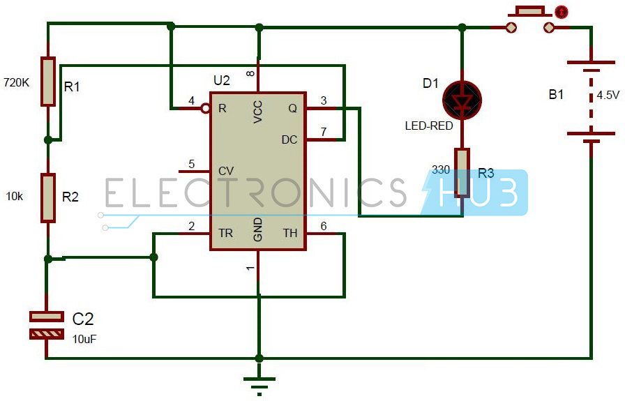
- 555 Timer IC.
- Resistors R1, R2, R3.
- Capacitor C1.
- High power Red LED.
- Battery.
- ON/OFF switch
Dummy Alarm Circuit Design:
This circuit consists of 7555 timer IC. It has 8 pins. First pin is connected to ground. Pin2 and Pin6 are shorted and connected to the positive terminal of the capacitor. Negative terminal is connected to the ground. A resistor of 10K is connected to the positive terminal of the capacitor. Another resistor of 680 ohms is connected in series to the 10K resistor. 7th pin is connected between the two series resistors. Other end of the resistor is connected to the battery of 4.5v. 4th pin and 8th pin are shorted and connected to the battery. In the circuit diagram, 8th pin is not shown. The LED with a resistor of 330 ohms is connected to the output pin from the timer i.e. 3rd pin.
Do you know about the Working of Super Sensitive Intruder Alarm Circuit?
Dummy Alarm Circuit Working:
- Initially switch on the circuit.
- Now press the ON/OFF button.
- By closing the button, one can observe LED glowing continuously with a delay of five seconds. This is because when the circuit is powered voltage is applied to the capacitor through two series resistors.
- At the same time, 555 timer IC also gets supply voltage.
- Thus capacitor starts charging up to a voltage of 2/3 VCC.
- When the charging voltage reaches to 2/3 of VCC, it is detected by the 6th pin and it connects 7th pin to the ground.
- Thus the capacitor starts discharging through 10K resistor.
- When the voltage in the capacitor reaches 1/3rd of the VCC, capacitor again starts charging.
- This process continuous which generates a wave with a delay of 5 seconds.
- This delay is decided by the RC circuit of the timer IC.
- The time delay can be calculated using the formula: T = 0.7*(R1+2R2)*C1.
- Using the above formula, one can calculate the values of resistance R1, R2 and C1.
- Thus using this RC circuit, one can produce exact delays.
- As the output is connected to the LED, it starts glowing with a delay of 5 seconds when a low pulse is detected at the output.
- Now release the button, the LED stops glowing.
Dummy Alarm Circuit Applications:
- As it produces exact delay of 5 sec, it can be used in timing applications.
- It can be used in cars for security that is, when any theft is detected in the cars it starts flashing for every 5 seconds.
Limitations of the Circuit:
- This is dummy alarm and it does not produce any sound, an LED is simply flashed for the given delay.
- Improper values of R1, R2 and C may cause improper time delays.
FAQs:
The 555 timer is used in astable mode to create a continuous blinking effect. This blinking LED mimics the status light of a real alarm system, making the dummy circuit appear functional and active, which helps deter intruders.
No, a dummy alarm circuit does not provide real security. It only creates the illusion of a working alarm system. While it may deter casual thieves, it should be used as a supplement to real security measures, not as a replacement.
You can control the blinking rate by changing the values of the resistors (R1 and R2) and the capacitor (C1) connected to the 555 timer. Increasing the capacitor value or the resistor values will slow down the blinking, and decreasing them will speed it up.
A 9V battery is commonly used for portability and simplicity. However, you can also use a regulated DC adapter (5V to 12V) depending on the components’ ratings. Ensure the power source matches the operating voltage of the 555 timer and the LED.
Yes! You can add a piezo buzzer to generate sound or integrate a PIR motion sensor to activate the dummy alarm only when motion is detected. These additions make the dummy system look more convincing, though they still won’t trigger real alarms or alerts.
Conclusion
A dummy alarm circuit that resembles the real security alarm system by using basic components like a 555 timer, LED, and a few resistors and capacitors. You can easily create a convincing visual deterrent to discourage potential intruders. While it doesn’t offer real protection, it serves as a useful supplementary tool in enhancing perceived security, especially in areas where full alarm systems may not be practical or affordable. We hope this guide helps you in creating a dummy alarm circuit.
Still having any queries? Feel free to share them with us in the comments section below. We will respond to resolve them promptly.

2 Responses
this is a very nice circuit
Why why why I tried making the circuit buy instead I used 680 k ohms but it is just blinking with no delay………wat should I do and am supposec to present tomorrow