During our journey through train and bus, we carry many important things and all the time we have fear that someone might lift our luggage. So to protect our baggage, we normally lock our baggage through old ways by the help of chain and lock. After all locks, we still remain in fear that someone may slash the chain and take away our valuable material. To overcome with these fear, here is an easy circuit which is based on the NAND gate. In this circuit, when someone tries to lift your luggage, it will generate a warning alarm which is very much helpful during your travel in the bus or train even at the night time as it can also produces audio visual indication attached to the relay.
Another application of this circuit is that you can employ these into your house so to avoid the attempt of robbery in your house with the help of this alarm circuit. When anyone tries to open the door of your house, loop break down and sound from the alarm produce.
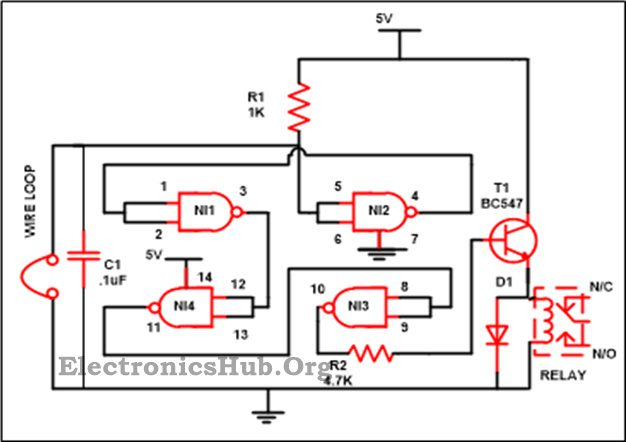
Luggage Security Alarm Circuit Diagram:
- IC
- IC1(CD4011) – 1
- Resistor
- R1(1K) – 1
- R2(4.7K) – 1
- Capacitor
- C1(.1uF) – 1
- Miscellaneous
- Relay – 1
- T1(BC547) – 1
- D1(1N4007) – 1
Luggage Security Alarm Circuit Description:
The basic building block of this circuit is CD4011 along with some other components viz. resistors, capacitor along with transistor and relay which is used to save your important things from robbery with the help of this easy circuit. It produces a warning beep, when someone tries to unlock the lock as an effect of its wire loop will split and alarm is produced.
To get familiar with the working, you should get aware with the NAND gate truth table which is shown below –
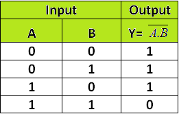
When any of the input states or both the input states go to the low state in the NAND gate, then the output will be high and if both the inputs are at high state, then the output will be low in that case.
CD4011 is the mainly used CMOS (Complementary Metal Oxide Semiconductor) chip. It arrives in a Dual Inline Package (DIP) of 14 pin. There is a small notch present on the chip at one of the corner which is recognized as pin 1. In a single chip, it is a group of 4 NAND Gate which are independent of each other. Each gate is a three terminal device with 2 terminals for the input purpose and one is for the output purpose. 5V to 16V is the working voltage range of the IC. Approximately 10mA of current at 12 V is been deliver by the IC which can be trim down with the reduction of the power supply voltage.
Related Post: Also Read the Interesting Post – Pull Pin Security Alarm System
Functioning of these circuits is very easy when we will receive; output is based on the voltage on pin 5. At the time when power supply is attached to the circuit pin 5, voltage is at zero as loop is unbroken. Hence at pin 4, voltage is high which is coupled with pin1 and pin 2 which is also at high state. As you can also find from the truth table of the NAND gate that if both the inputs are at high state, then the output is low hence at the pin 3 of gate 1, we get low which is once more attached to pin 12 as well as 13 moving them also to the low which in turn makes the pin 11 to switch at high switching pin 8 as well as pin 9 also at high and low voltage at pin 10 due to this transistor linked to it via a resistor will not boost the base of it and the alarm will not receive by us. This implies that our baggage is secure.
Now suppose that someone attempt to take your baggage then the loop attached to it broken down. At the time loop break down, pin 5 as well as pin 6 shift to high and just opposite work will take place which we will explained above due to which pin 10 reaches to high state and transistor begin its conduction and alarm is receive by us.
And the alarm will not stop till the time we once again interact with the loop. Based on the rating of the relay that you are using in your circuit value of the battery will vary in the range of 6-15V. If you wish, you can directly fix the buzzer without using relay. We are using the relay in our circuit because if anybody wants to connect the alarm directly with the AC, then also it will work without making any damage. Diode is also fixed in our circuit because if there any spikes of the reverse voltage, then it will be short-circuited at the source itself and there will be no damage done by it.

18 Responses
i want can i connnect the output of sensor directly to the input of the logic gates
Don’t mean to seem critical, but isn’t the 4011 completely redundant? The circuit will work exactly the same with R2 connected directly to R1 and the loop.
How will the circuit recognises whether the laggauge lifted is owner or the thief?
can i build this circuit without using relay ,if yes then how ??
Relay is just to indicate open circuit.You can simply replace it with a buzzer.
I want to know using NAND, NOT gates for security lock.
where we have to connect buzzer or led???
I want to know how will I connect my luggage to my circuit and how will I switch off the alarm if I want to access my luggage. if anyone knows the answer please do reply. Thanks in advance
Can I know how much this original project cost
?
Just 150/- rupees
what is the use of NAND gate?
Can we use only two nand gate?? why 4 nand gate??
What is the function of the capacitor and the transistor?
CAN U PLEASE PROVIDE ME DOCUMENTATION ON ABOVE TOPIC(luggage security……….)
This project is awesome.but I need to connect to Mobile.so that I can racgnise easily
Why cant we use 2 NAND gates instead of 4? Wont the output be same?
Why we use 4 Nand gates instead of using 2 Nand gates ? Can anyone please explain me ?
I like this project very much .
Hey can u please provide me the video if this project.
I didn’t find any videos on this topic .