This circuit will help you to guard your precious documents as well as jewellery from intruders or theft. All you need is just to place this circuit in front of the locker or below the mat so when any unknown person come and walk over the switch, the circuit will trigger and sound of alarm comes. The main benefit of the circuit is that these can be implied in two places at a time as two different switches produces two different sounds.
Circuit Diagram of Security Alarm:
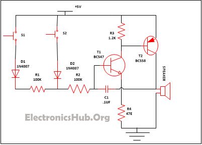
Security Alarm Circuit Components:
- Resistor
- R1, R2 (100K) – 2
- R3 (1.2K) – 1
- R4 (47E) – 1
- T1 (BC547) – 1
- T2 (BC558) – 1
- D1, D2 (1N4007) – 2
- C1 (. 1uf) – 1
- S1, S2 – 2
- Speaker – 1
- Resistor: Resistors are the passive device with two terminals. They are mainly used in the circuit to restrict the flow of current across any of the circuits. The current flow from the resistor is directly proportional to the voltage that is given across the terminals of the resistor. In the market resistors are mainly available in two broad categories:
- Fixed resistor– It actually means that the resistor whose value cannot be change and remain what its mark on it.
- Variable Resistor- It means that the value of resistance can vary within the range marked over it. For e.g. If the value of 5k is marked on it then it implies that the value of the resistor can vary from 0-5k.
- The value of the resistor can be calculated either with the help of multimeter or with the help of color code over the resistor.
- Diodes – It is a device with two terminals and have a asymmetric attribute which means that it permit the flow of current in one of the directions while the flow of high resistance is from another direction. Hence in it flow of current is in one way only and block the other way for the current flow. The two terminals in diode named as anode and cathode. AC current can be converted into DC with the help of diode unidirectional behaviour.
- Transistor – transistor is a three terminal electronic device used to amplify weak input signals. A transistor consist of two PN junction diode connected back to back. Transistor are of different type such as bipolar junction transistor, Field effect transistor and photo transistor. They are mostly used in electrical appliances due their smaller size and light weight. In addition they posses less power hence have greater efficiency.
- Speaker- it is a transducer which creates sound in reaction of the electrical auditory signal given in the input.
- Capacitor– Electric charges are being stored by these two terminal components which is passive by nature. A dielectric medium is used which is used to separate two conductors. It started at the time when the potential variation occurs in the conductors polarizes the dipole ions to hold the charge in the medium which is dielectric. There are two varieties of capacitor available in the market –
- Polarized capacitor- Capacitor marked with – and + sign. They are mainly used to hold the charge. And before troubleshooting these capacitors carefully discharge them as they hold charges there is a risk of shock.
- Non polarized capacitor – Capacitors which do not have any polarity marked over it. They are mainly used to remove the noises appeared while converting AC into DC.
Important Post: Pull Pin Security Alarm Circuit
Working of Security Alarm Circuit:
S1 and S2 are the two switches that are used in the circuit so that both can be put in two different places i.e. one of them can put in front of the locker while another one can be placed on the front door. When the switch S1 is pressed diode D1 which is linked with it starts conducting as the transistor T1 and T2, which is attached with the resistor begin its conduction. For the oscillation purpose Transistor T1 and T2 gets a positive feedback which is provided by capacitor C1. The presence of any intruder is indicated by the low tone frequency which is generated when switch S1 is pressed.
Same kind of condition occurs when switch S2 is pressed. Diode D2 which is linked with the switch S2 begin its conduction and offers power supply the transistor T1 and T2, which is in the waking state and as a result sound comes from the speaker attached to it. But in this instance a high frequency tone comes out which is a sign that there is some intruder present around the locker. The sound that came from the speaker can only be stopped by cut off the power supply.

34 Responses
Hi,
Nice circuit
I have just seen UR Circuit. Any how it seems to be good and useful for domestic use and I will try soon. ThanQ for publishing such useful circuits.
hi it is a nice circuit and very useful for domestic purpose.it give a safety as well high sequirity for expensive things.thank u for publishing
hi… its a very nice circuit…
Its a cool circuit but I failed to understand the type of switches used, are they mechanical or Sensor operated switches? But this is realy an awesome circuit. Thanks for the Answer to come.
These are limit switches ( SPST ).
Thanks for providing such useful information about this circuit….
should i get the proteaus simulation of this circuit
nice,it very useful .but diagram not display
diagram not display
useful ckt
is the switches are sensors?
They are simple push buttons
Can i use normal switches or pushing switches
You can use push buttons
please give the detailed description of security alarm..
yes!! thus really a nice and easy circuit to buid at home
this really good &simple circuitry
can i know why pnp & npn trasistors are used?why don’t both pnp or both npn trasistors
R4 VALUE AND WHICH TYPE OF SPEAKER OR BUZZER
DO we want to use the switches as sensors ?? or we can use the normal switches??
You can use normal switches
What is the disadvantage of simple security alarm?
Disadvantage of simple security alarm
excellent circuit can u please send a pdf on this ckt
Hi sir ! how much is the cost of this circut ? if i select it as a final project con yuo help me about the hardware and code of this circut ?
thanks sir i wait to your response ….
welldone. but put an easy diagram.
i want video for this circuit
can we do this project in online using topspice
What is
Resistor 47 e
Anusha, please answer this comment. And can i ask the value of the speaker
hi! can you design circuit that can use for four doors ?
Which transister can I used as alternate of BC558??
Can you explain me what is role of capacitor in circuit with fully explanation? And power supply is dc 5v right?